The Sleep Sensei

The Sleep Sensei is a device I created to help people fall asleep faster using calming breathing training. It’s for people who have trouble falling asleep, due to insomnia or an active mind at bedtime.

I ended up posting the Sleep Sensei on Kickstarter and had a successful campaign.

You can read more about the Sleep Sensei here: www.getsleepsensei.com

This post is the story of the Sleep Sensei and how it came to be.

The first (very rough) prototype

This whole project started because I have trouble falling asleep at night. I was looking at potential solutions and came across a smartphone app that produced a pattern of light to follow with your breathing as you try to fall asleep. The main problem with this is that the phone screen is so dim that you can’t see it without having your eyes open! This seemed counter-productive to sleep, so I sought a better way.

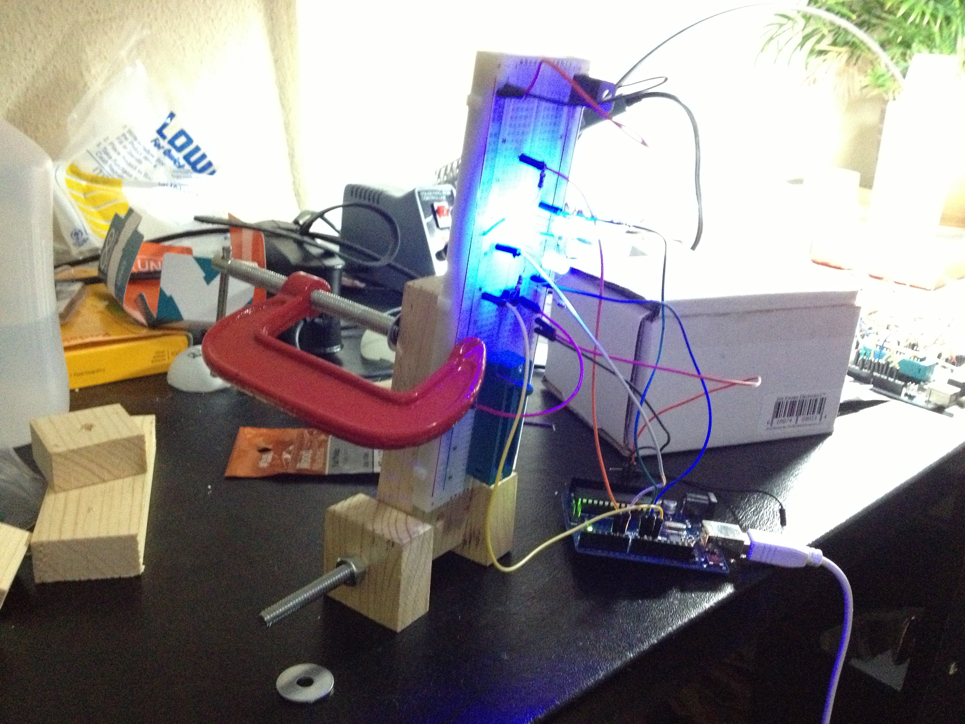
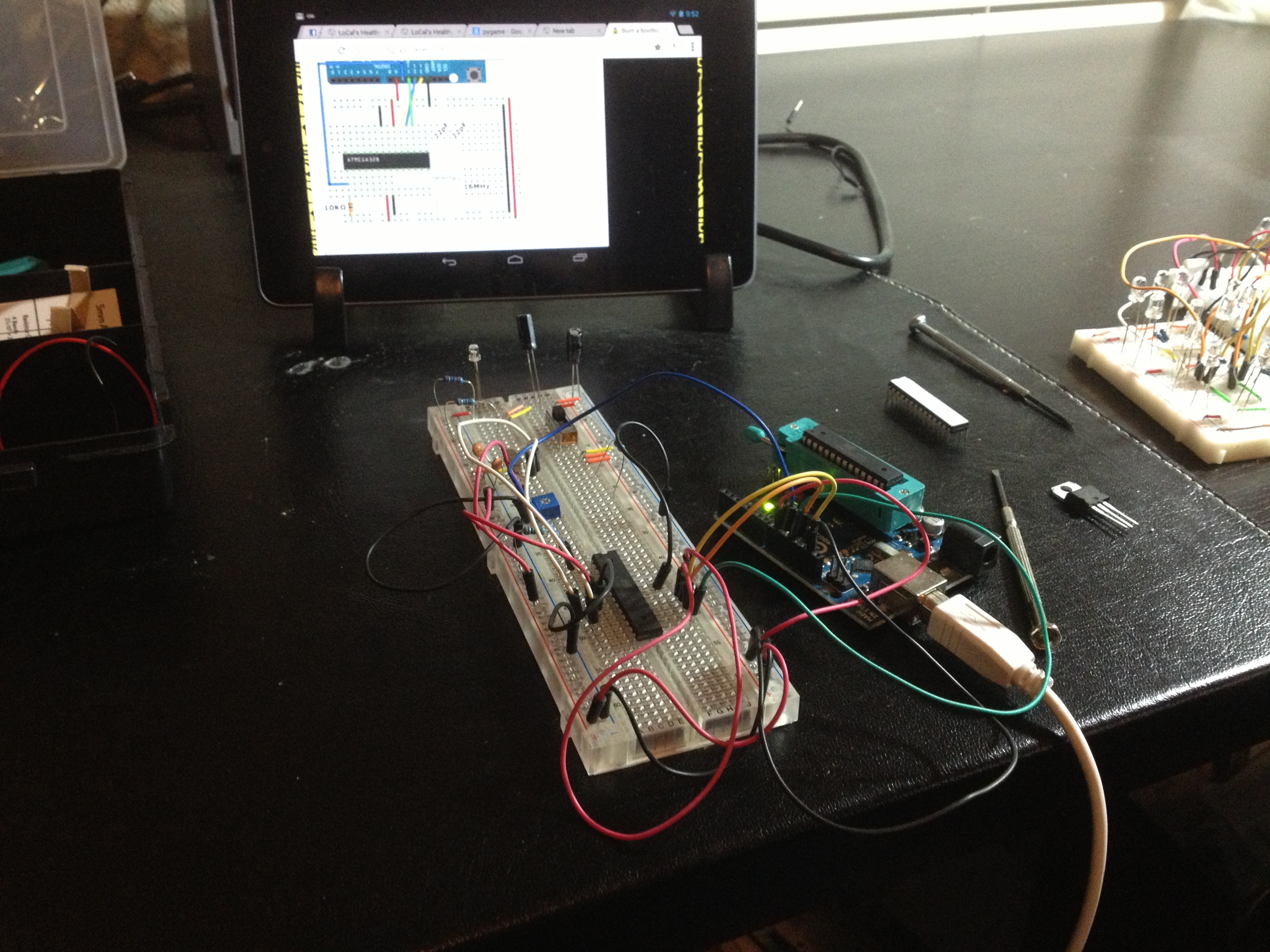
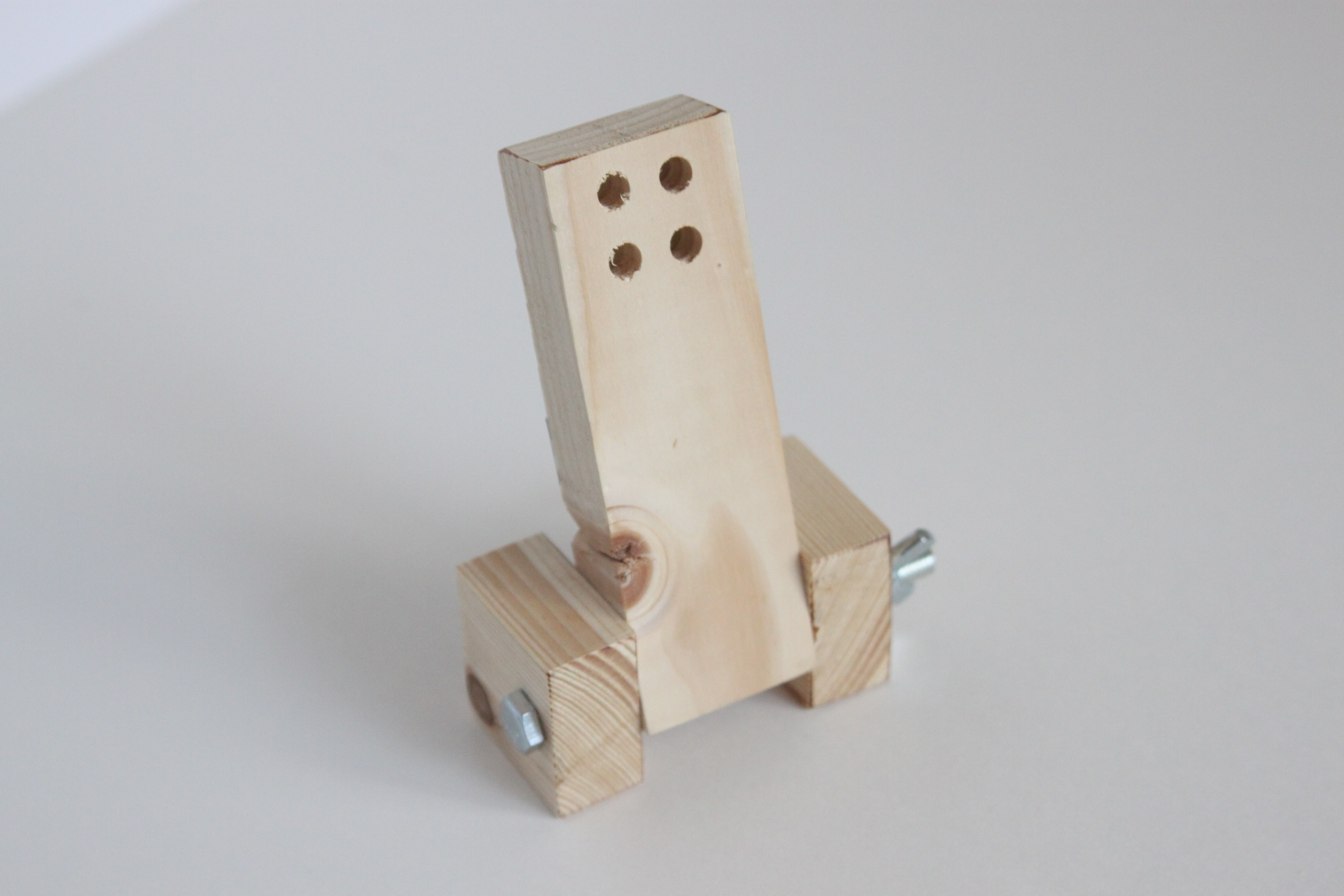
This is the very first prototype of the Sleep Sensei. It consisted of a breadboard with 4 blue LEDs performing a simple brightening and dimming cycle. I chose blue LEDs since the smartphone app I used performed a similar feat, and it used blue light. This was before I began researching the effects of various colors of light on sleep quality, so I didn’t really know any better.

The breadboard was clamped onto a wooden base with a pivot to allow me to aim the light towards my eyes. The idea was that the light from 4 LEDs directed towards my eyes would be bright enough to be seen with my eyes closed through my eyelds. And it worked!

More prototyping, and the Kickstarter design

Standalone Prototype

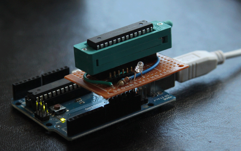
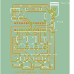
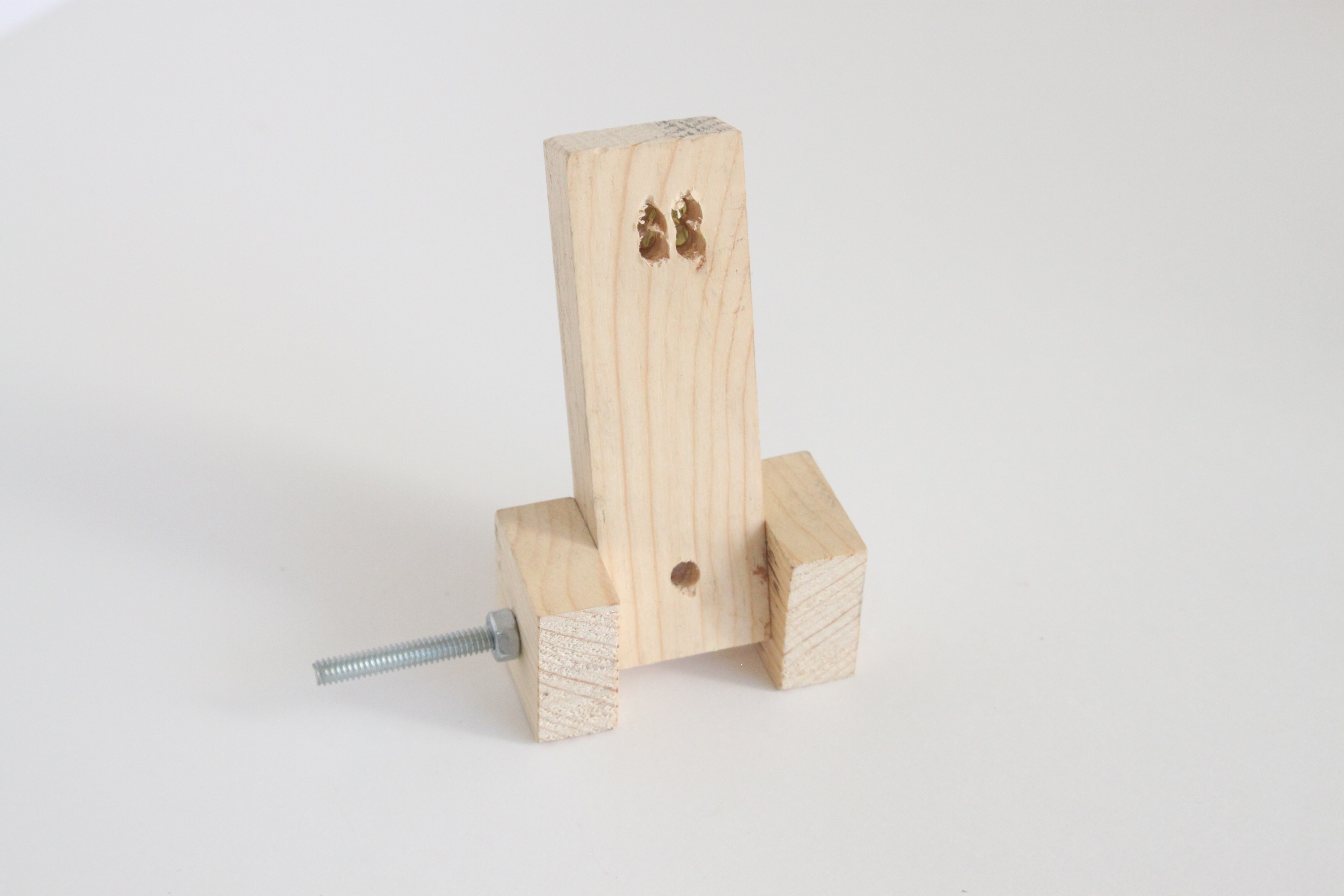
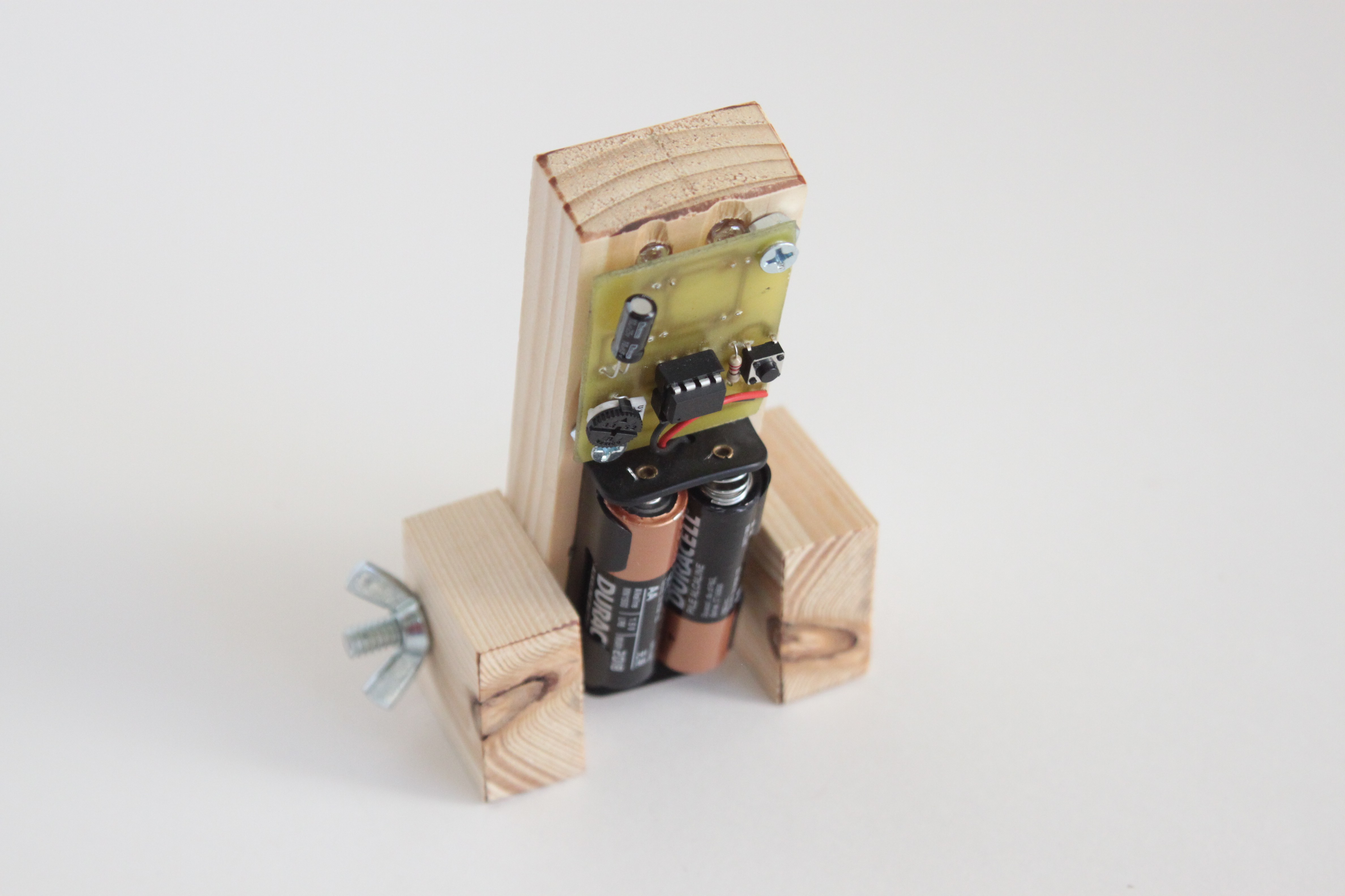
I liked the idea of the Sleep Sensei enough to acid-etch a circuit board for what I breadboarded. I drilled 4 (very rough) holes into my wooden base so that the LEDs would shine through, and had my first standalone prototype!

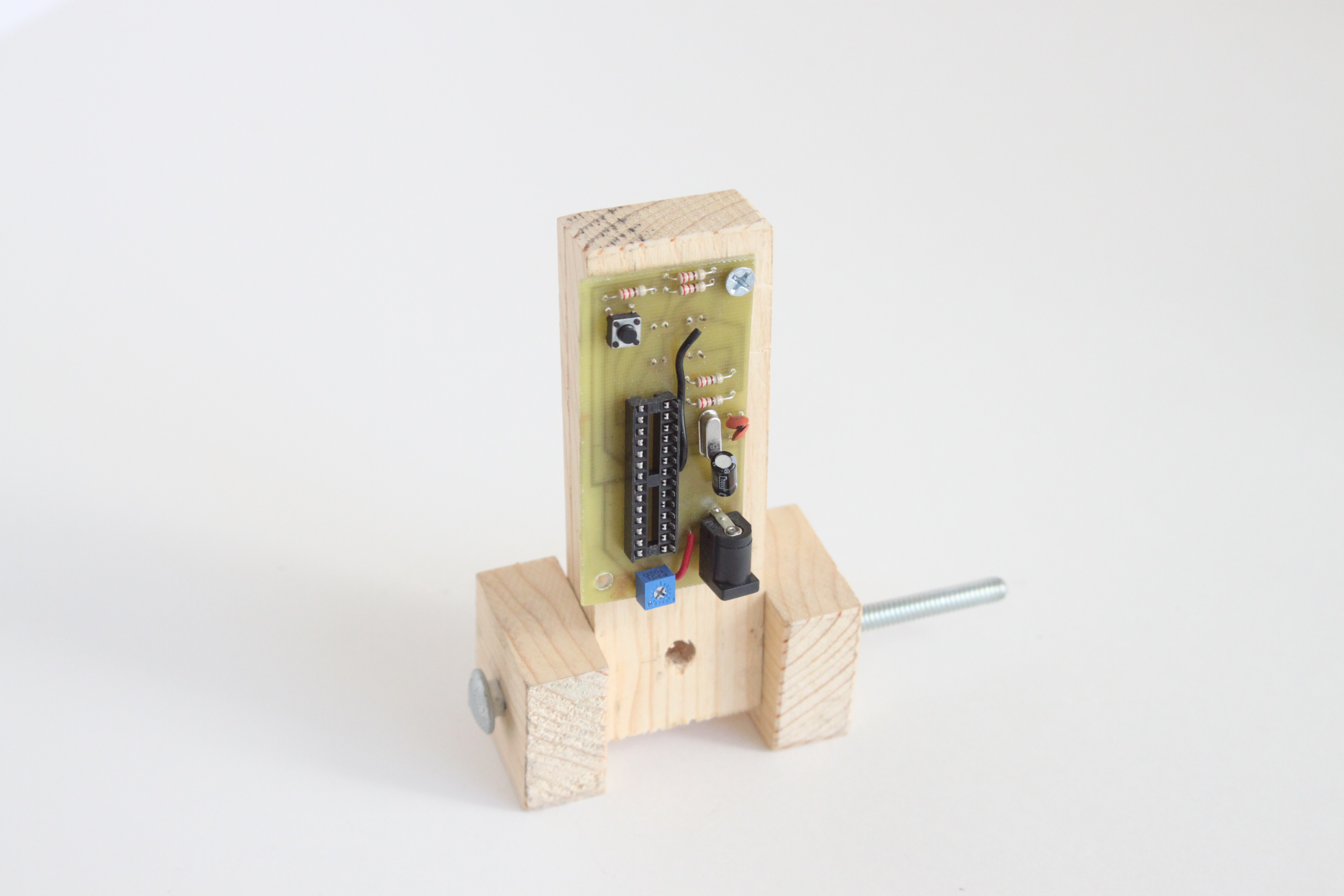
This prototype used an ATMega328, and it has a standard potentiometer to adjust the brightness. The button would allow you to switch between 4 durations of sleep coaching.

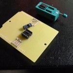
The First Decent-Looking Prototype

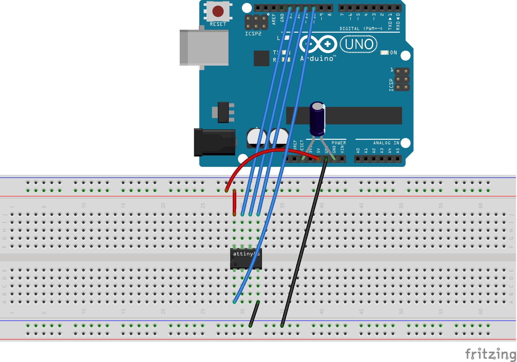
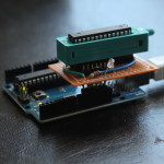
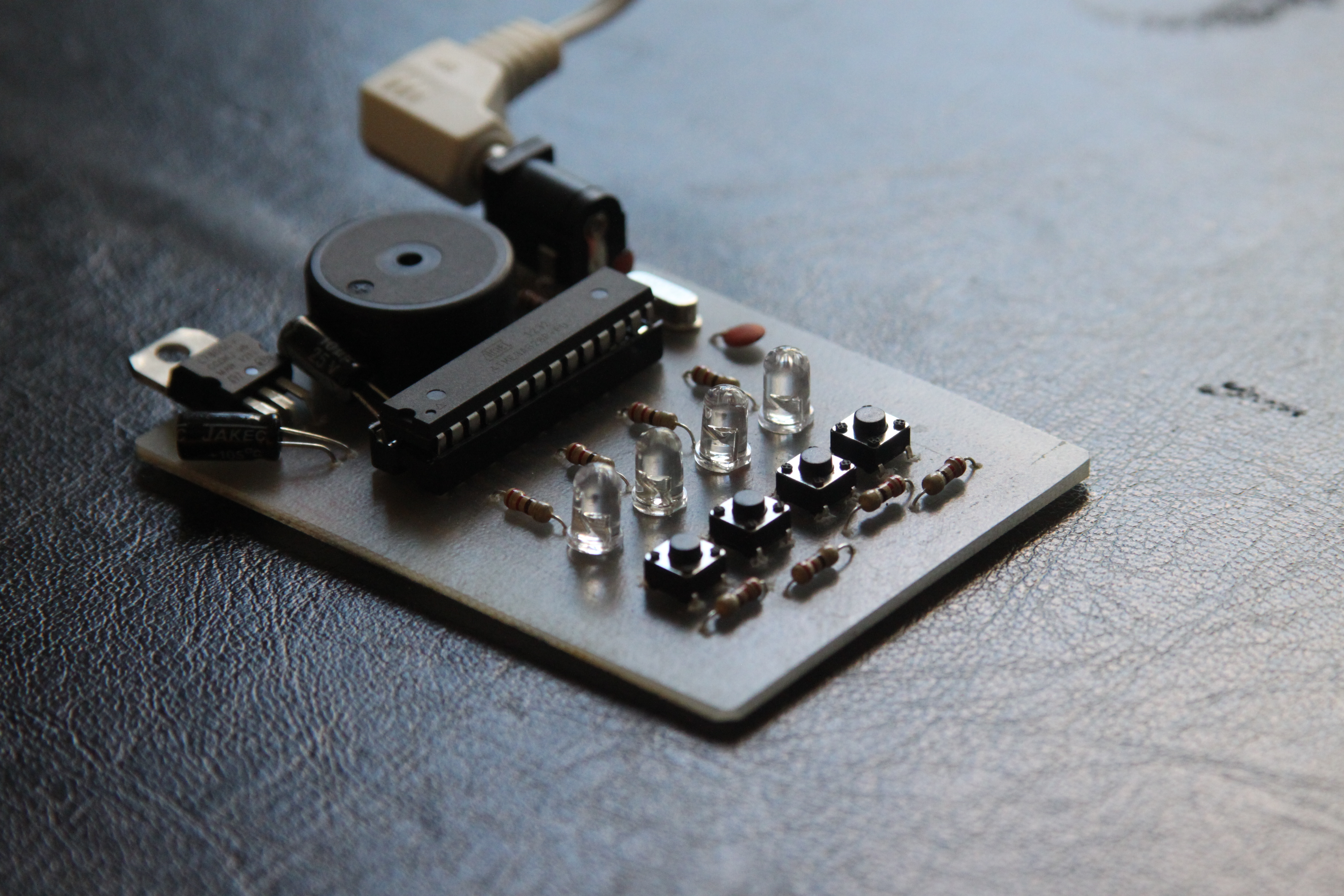
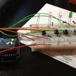
I ended up enjoying using my standalone prototype so much that I wanted to try to make more of these little guys to try on friends and family. I figured if it helped me fall asleep faster, it could help others as well. So I did some research and found out that I could program an ATtiny85 (much cheaper than the ATMega328) using Arduino, and whipped up a breadboard with all the necessary connections.

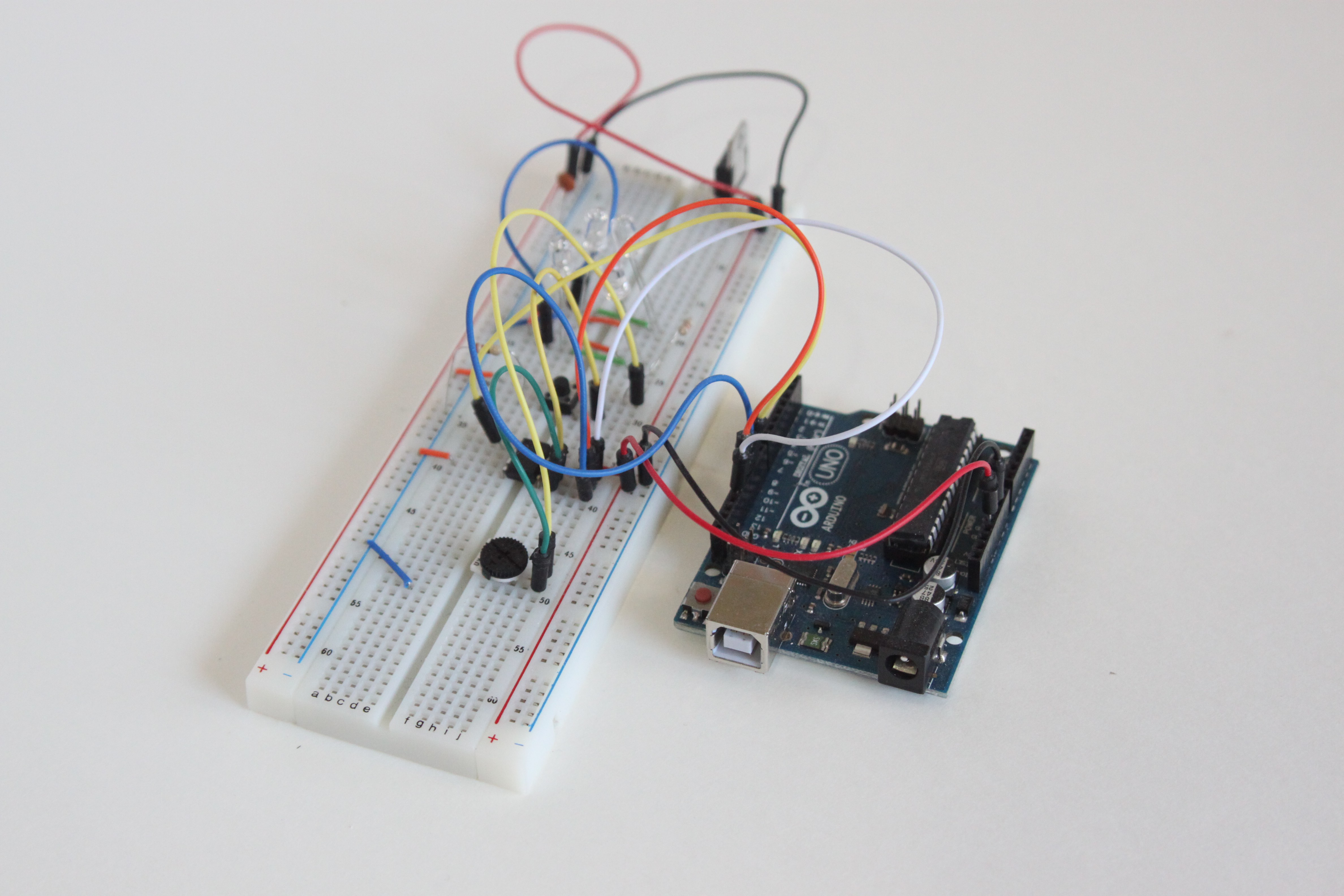
A challenge I had was timing, since the ATtiny85 was running at 8 MHz compared to the ATMega328’s 16 MHz. So I had to add a couple multiplication factors in the code to have the breathing pattern match what I had tuned on the ATMega-based design.

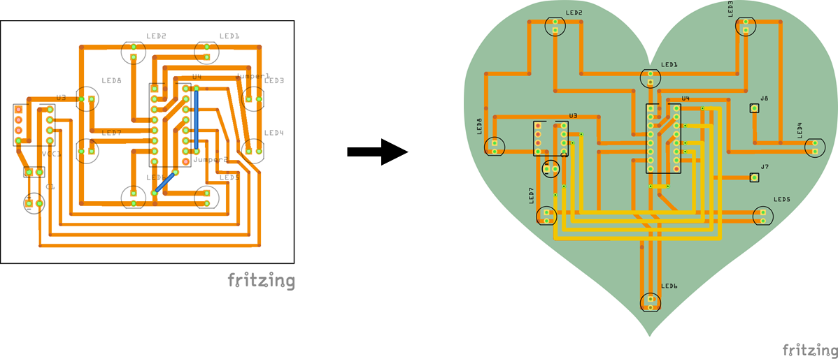
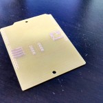
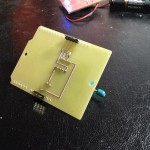
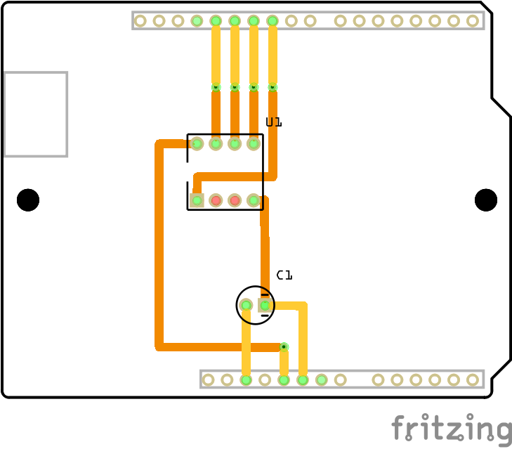
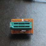
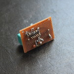
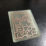
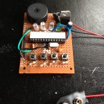
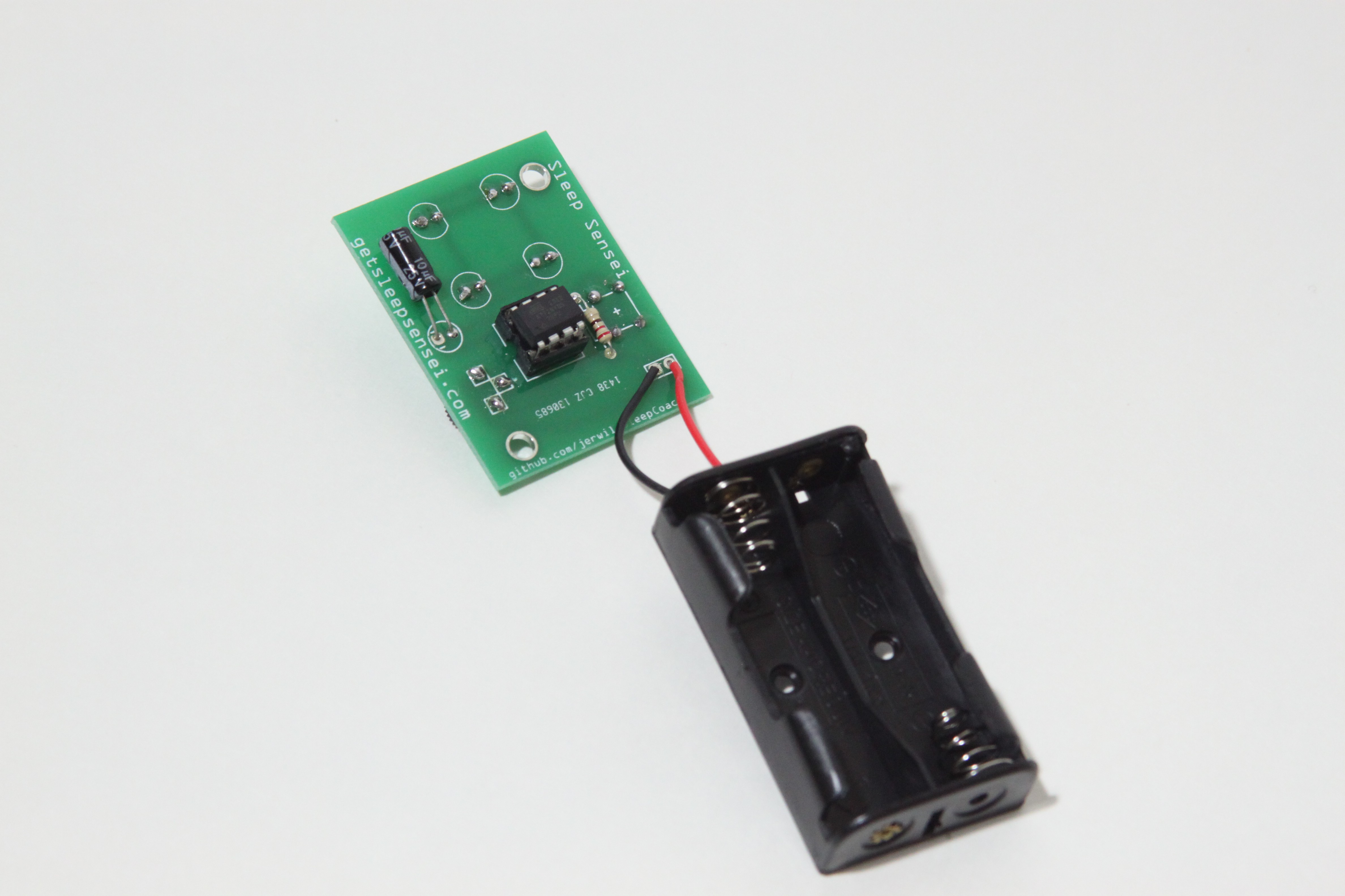
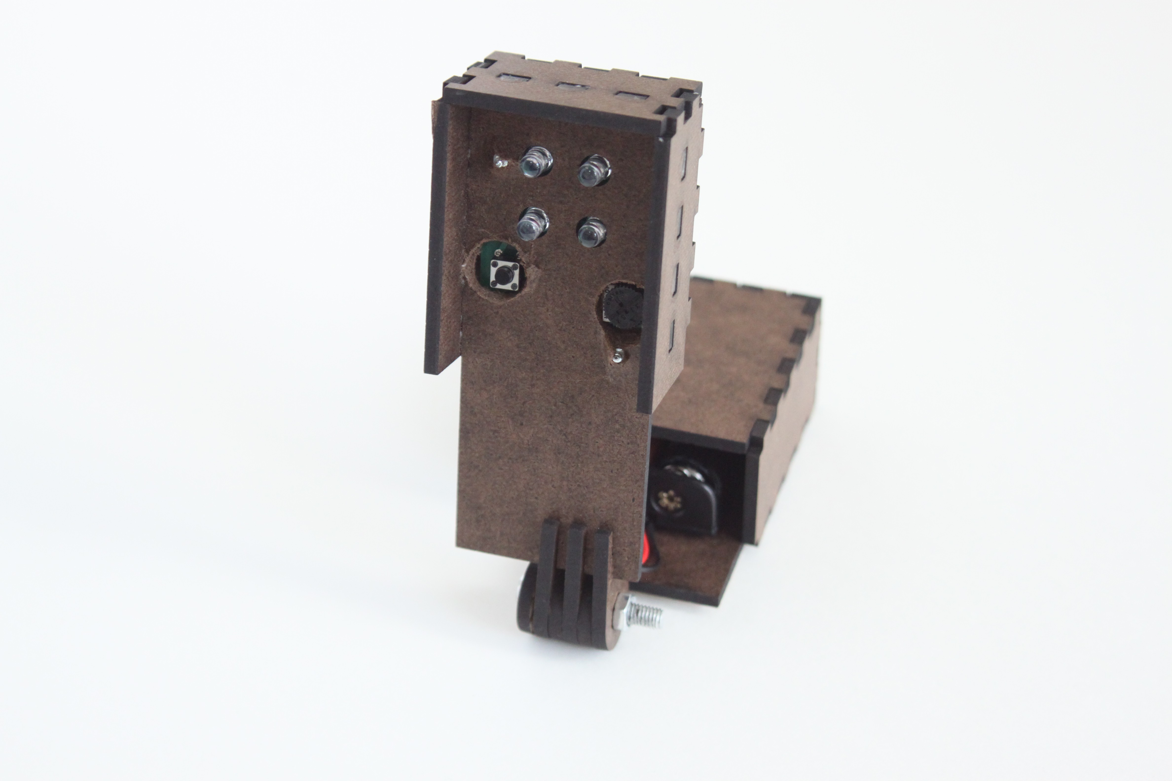
I then designed and acid-etched a new circuit board designed for the ATtiny85. I also found some nice thumb-wheel potentiometers on eBay which would allow for adjustment of the brightness without a tiny screwdriver. Here is what the prototype looked like:

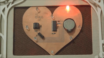
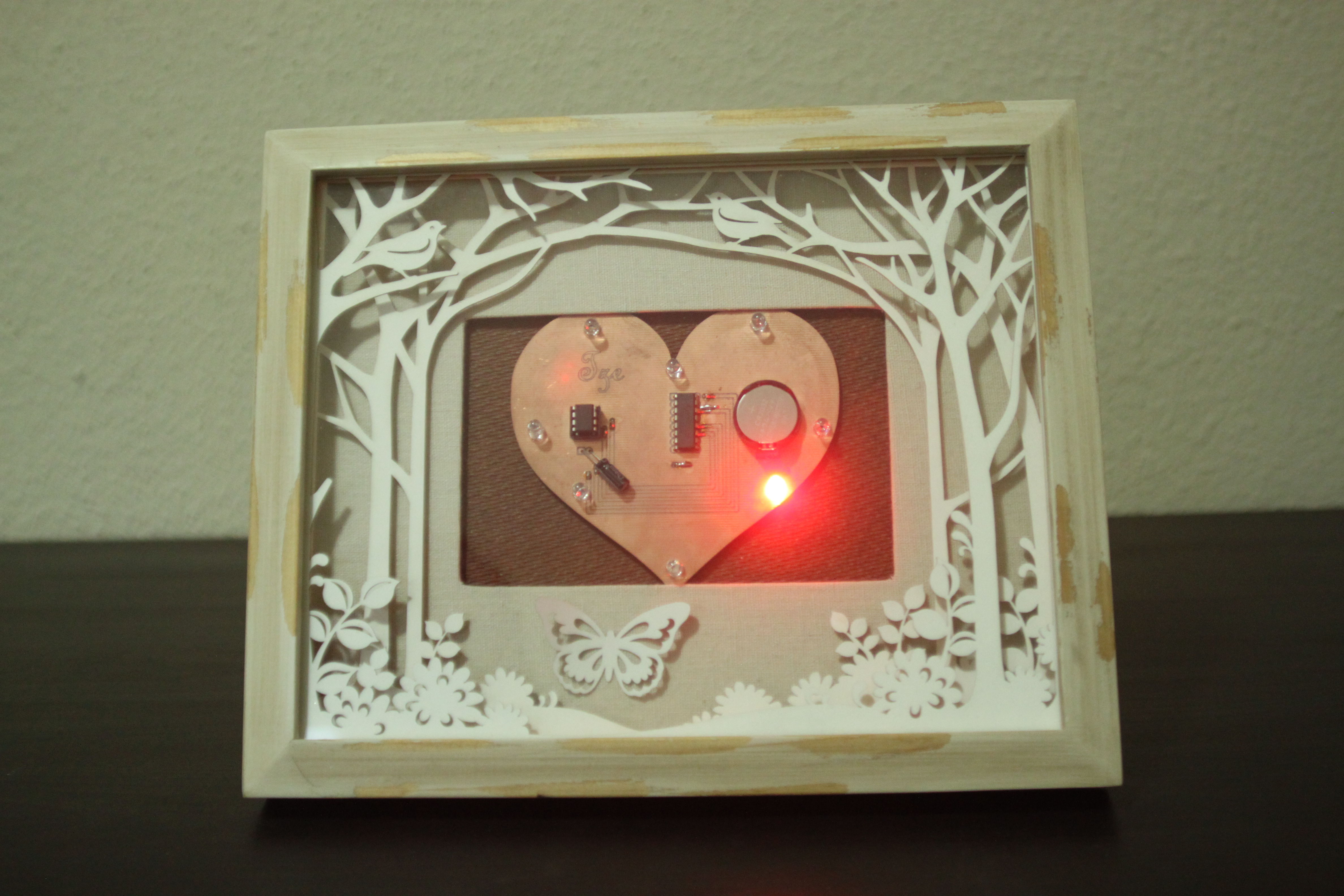
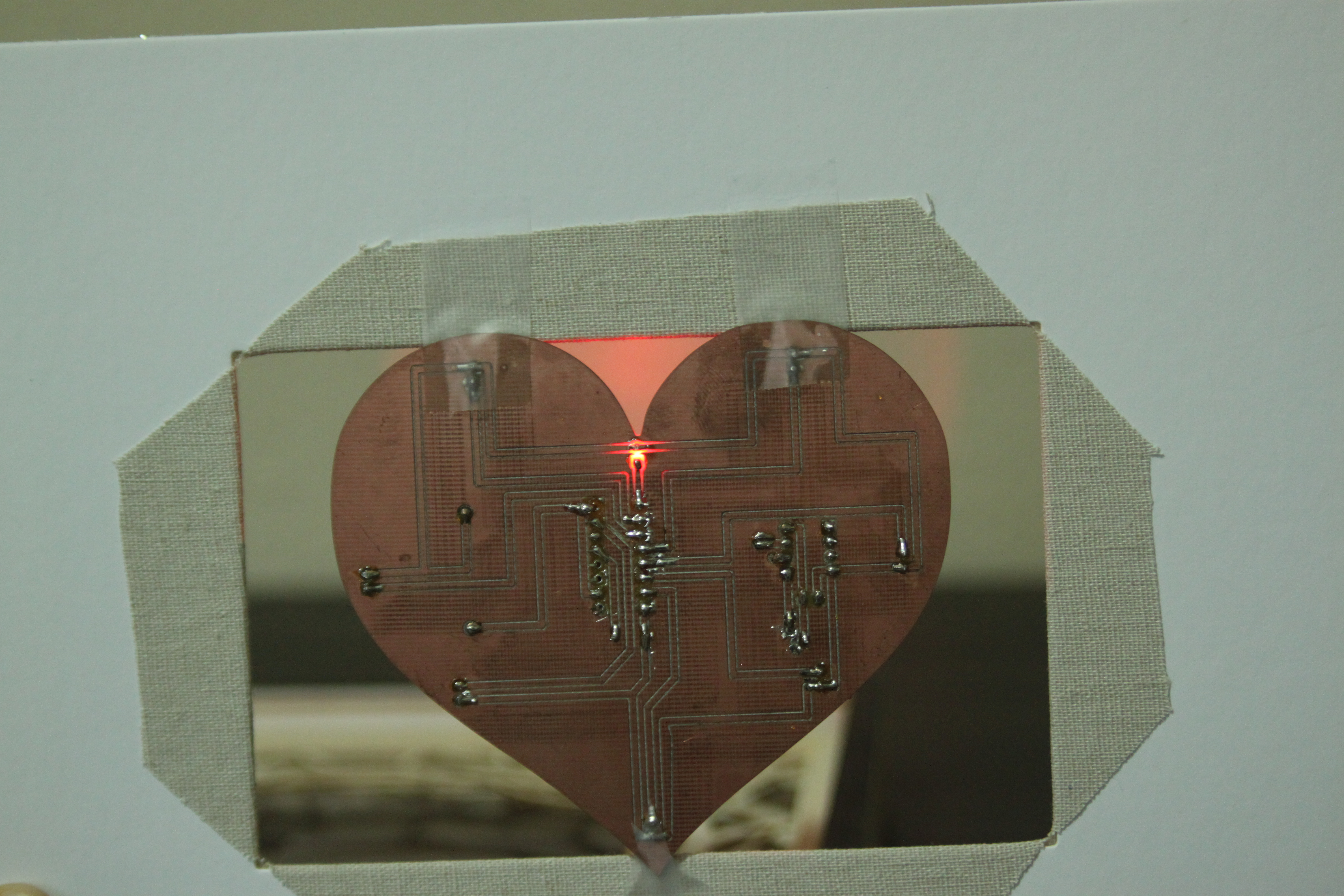
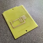
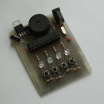
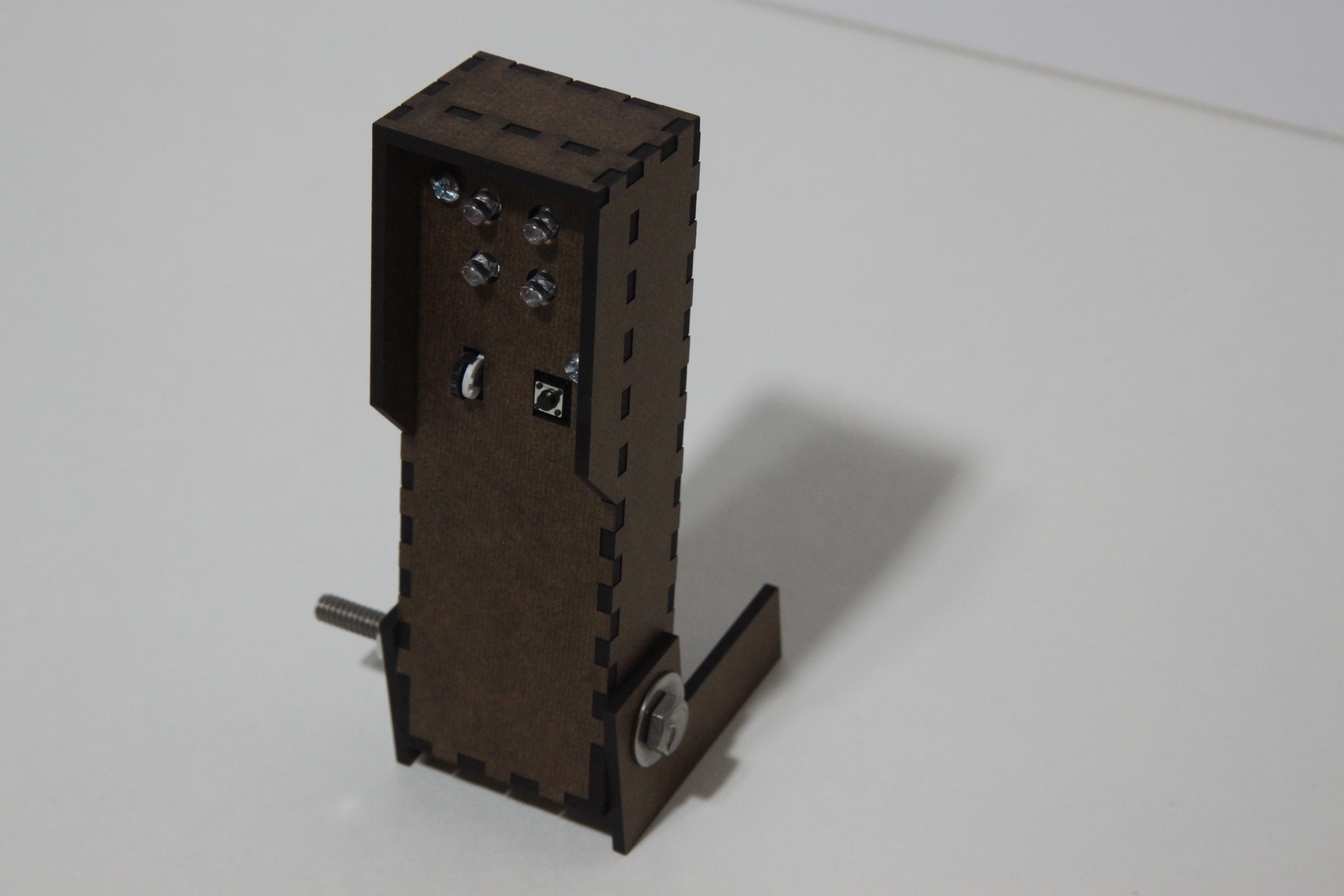
I used this guy for a few weeks, and it was actually pleasant to use. This time I had red LEDs (since I had done some research), and a nice compact circuit board that wouldn’t be too expensive to have professionally made. So that’s what I did:

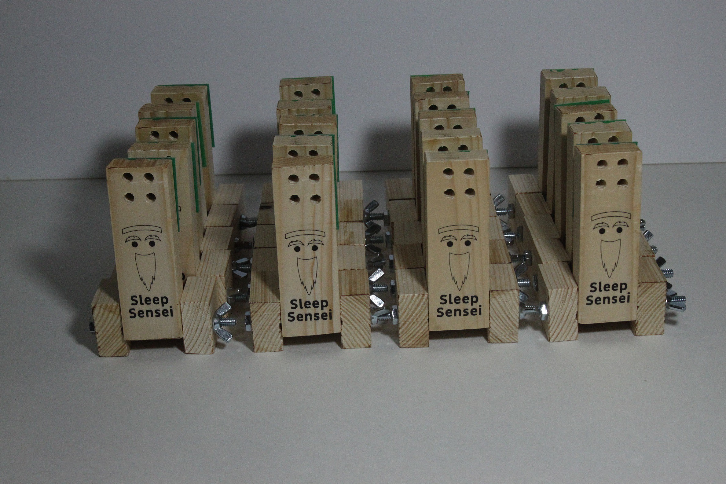
I wanted to test the product out in the wild and get feedback, so I came up with a (terrible) logo for the Sleep Sensei and made a small army of them!

The Sleep Sensei Study

At first, I gave my prototypes to a handful of friends for their feedback. They responded with things like “it seems to work” or “I think it might be helping.” Although it was great to get positive feedback, I wanted results that were a little more scientific. So I came up with a study of sorts.

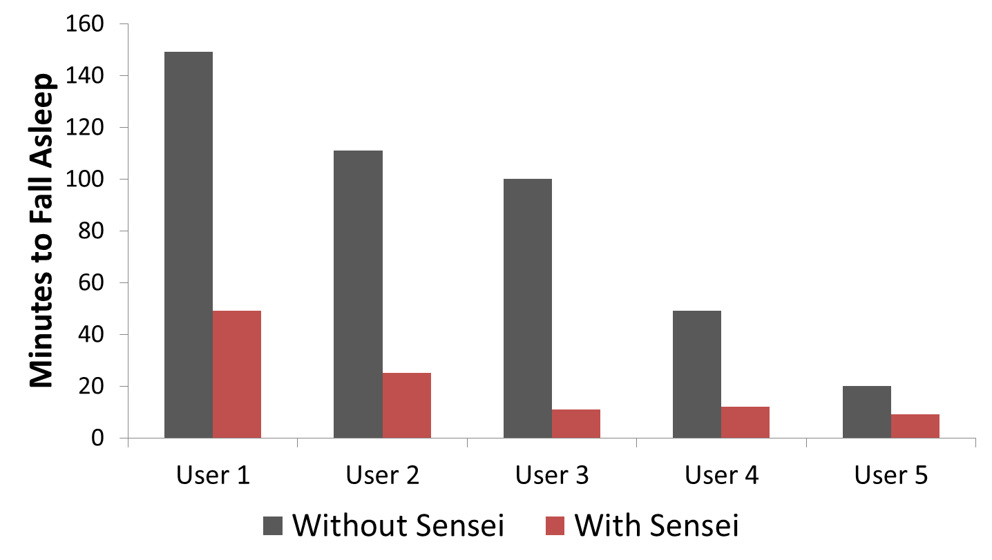
Using this ad, I found several people on the reddit /r/insomnia community willing to try the device and provide me data on their sleep via a daily survey and seep tracking smartphone app. I had the users record data for 3 weeks without the Sleep Sensei, and I then sent the users the sleep coach device and had them record data for 3 weeks of sleep using the device.

I ended up sending out 20 Sleep Senseis, and I got decent data from 5 users. Here is a plot of the average time it took these users to fall asleep before and after using the Sleep Sensei:

I have a detailed breakdown of each user’s data here.

Here is some of the feedback I got from the users:

“I think the quality of sleep has been improving, and I think that’s the Sleep Sensei. When I start having issues again I pull it out and it does help” – Alice S, TX

“I was really impressed with the [Sleep Sensei]- it cut the amount of time it took me to fall asleep by about half … I basically don’t have insomnia anymore and it feels that way” Marijke S, MA

“The [Sleep Sensei] allows me to fall asleep in at least under 30 minutes, sometimes even as few as 7 minutes, which is great for me! I would definitely recommend this device to anyone who is on the search for something new to help them fall asleep, someone who perhaps has tried every other sleep aid without finding anything that truly helps yet. The Sleep Sensei is awesome!” – Kate B, GA

“I’ve noticed a HUGE decrease in how long it takes me to fall asleep which has been wonderful! I really like the machine. It’s easy to use and works well.” – Kelly P, LA

Of course, this was not a clinical trial or very hard-sciency, but it gave me the confidence to try to make the Sleep Sensei into a real product by launching a Kickstarter!

The First Kickstarter

With a bit of confidence under my belt, I decided that I wanted to launch a kickstarter for the Sleep Sensei to get it into more hands.

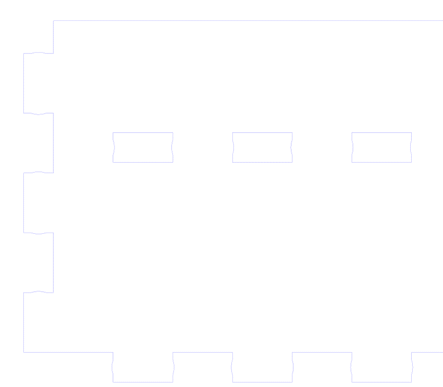
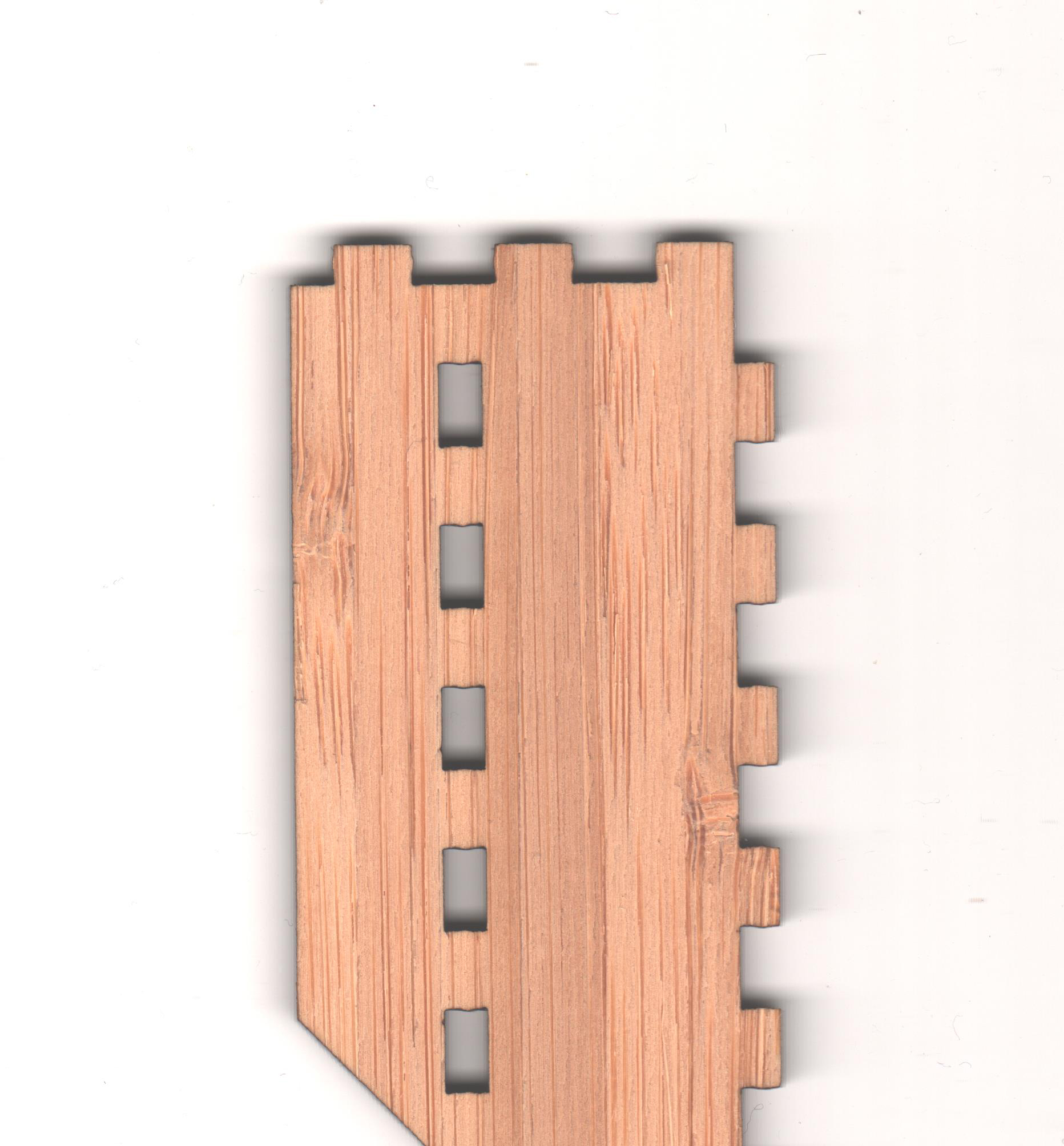
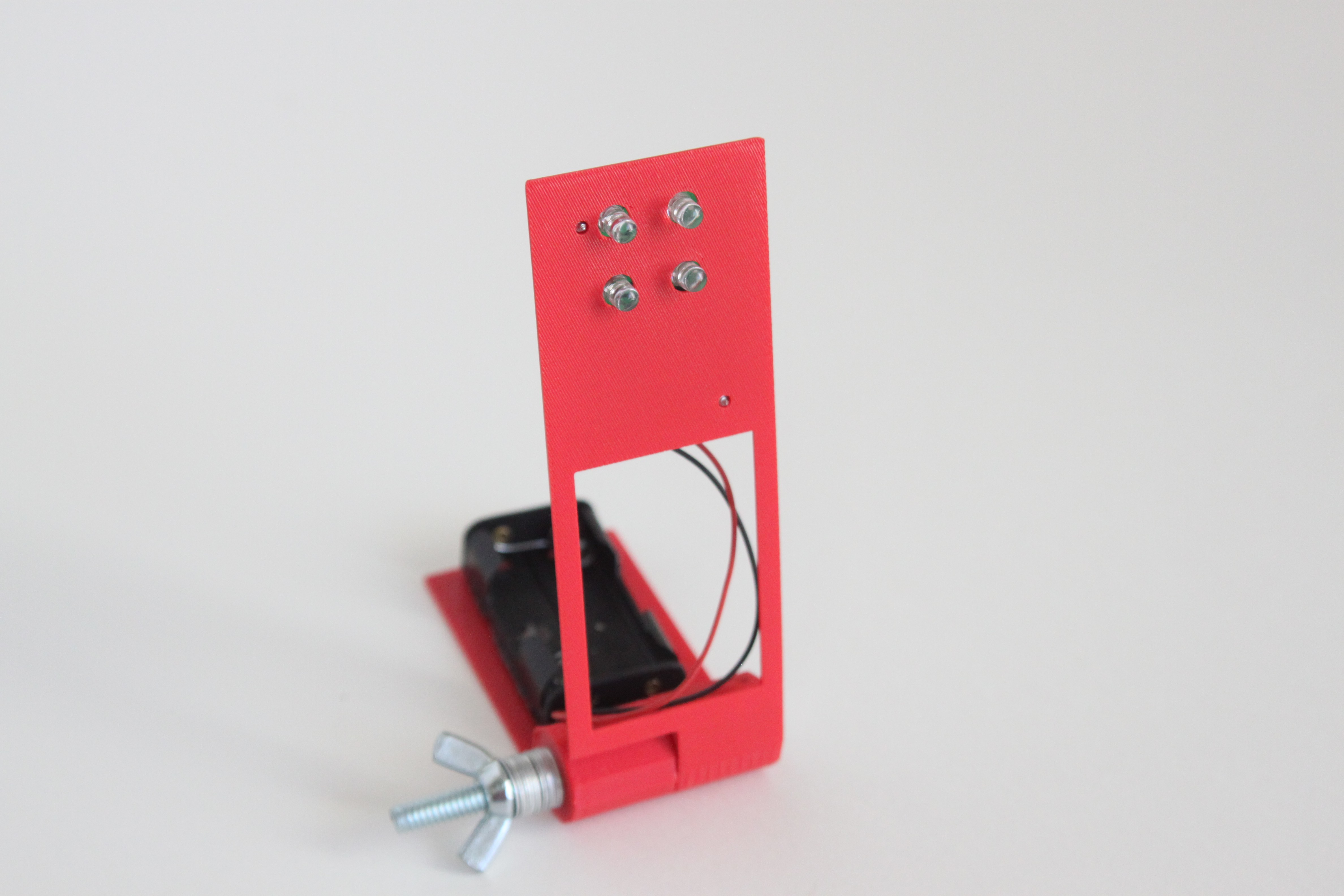
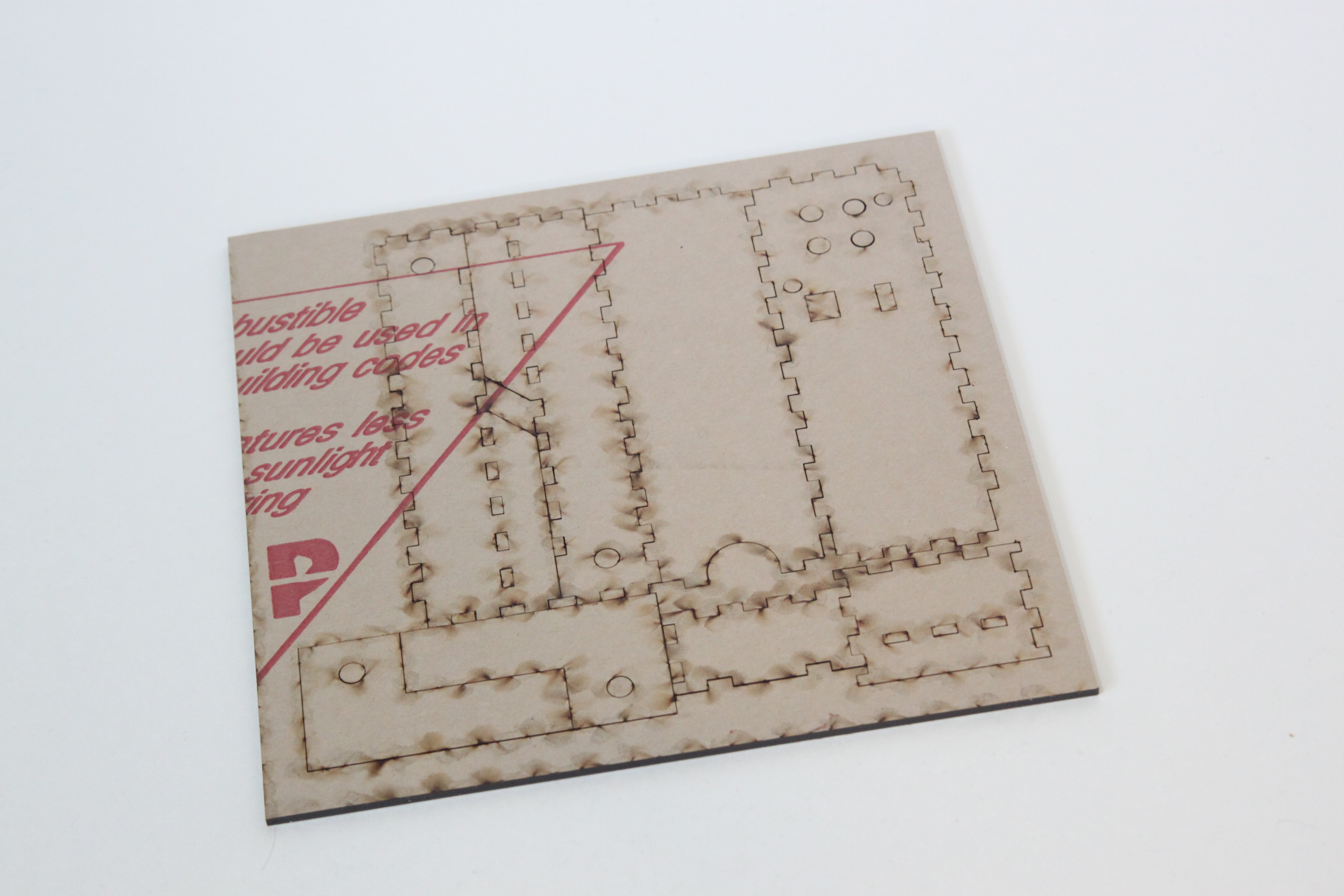
I was tired of having to make my own wooden bases by hand, so I started working on a new design that could be fabricated by a vendor. I ended up trying out a bunch of concepts, such as:

Split laser-cut design

3D Printed minimalist

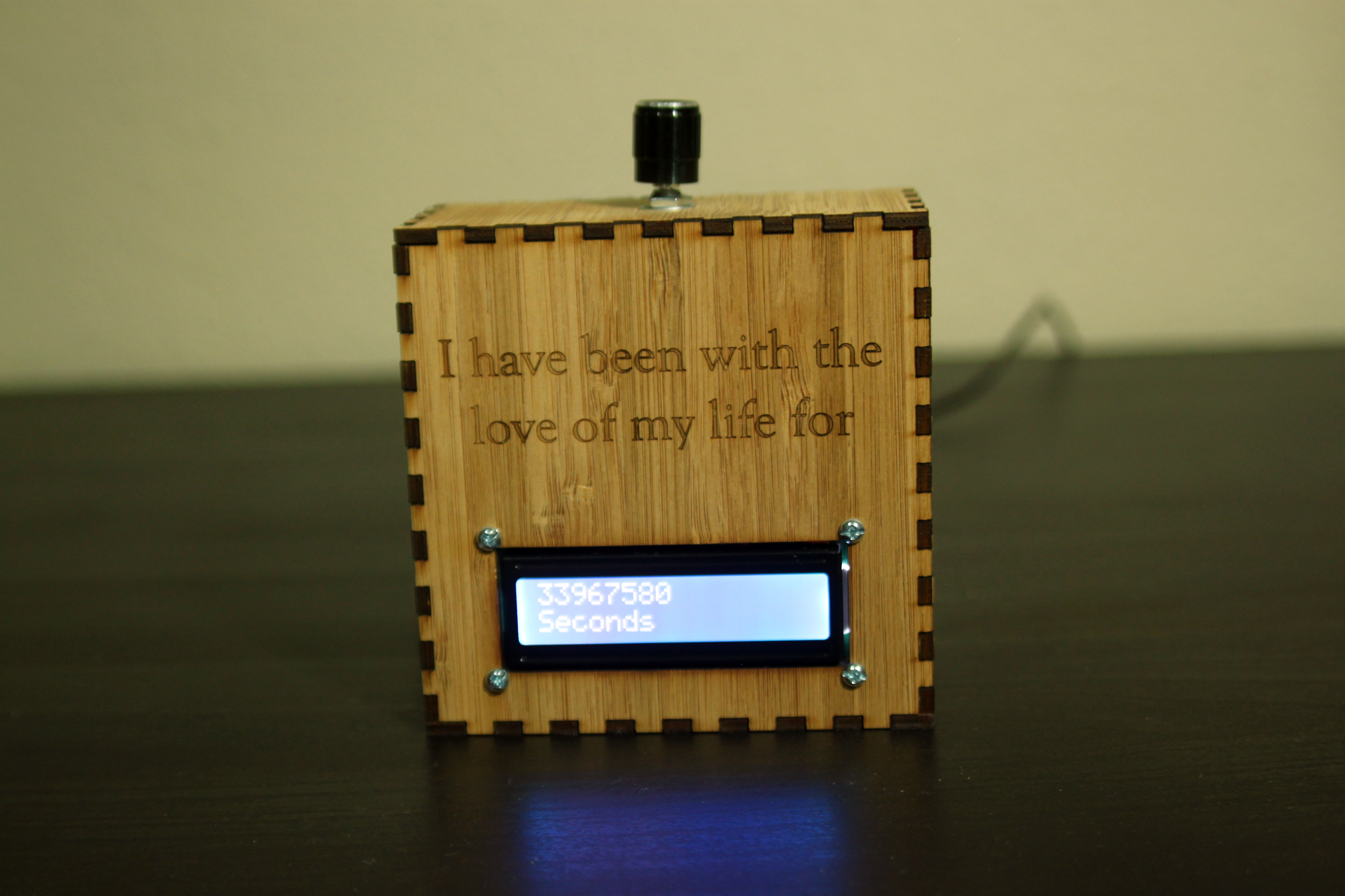
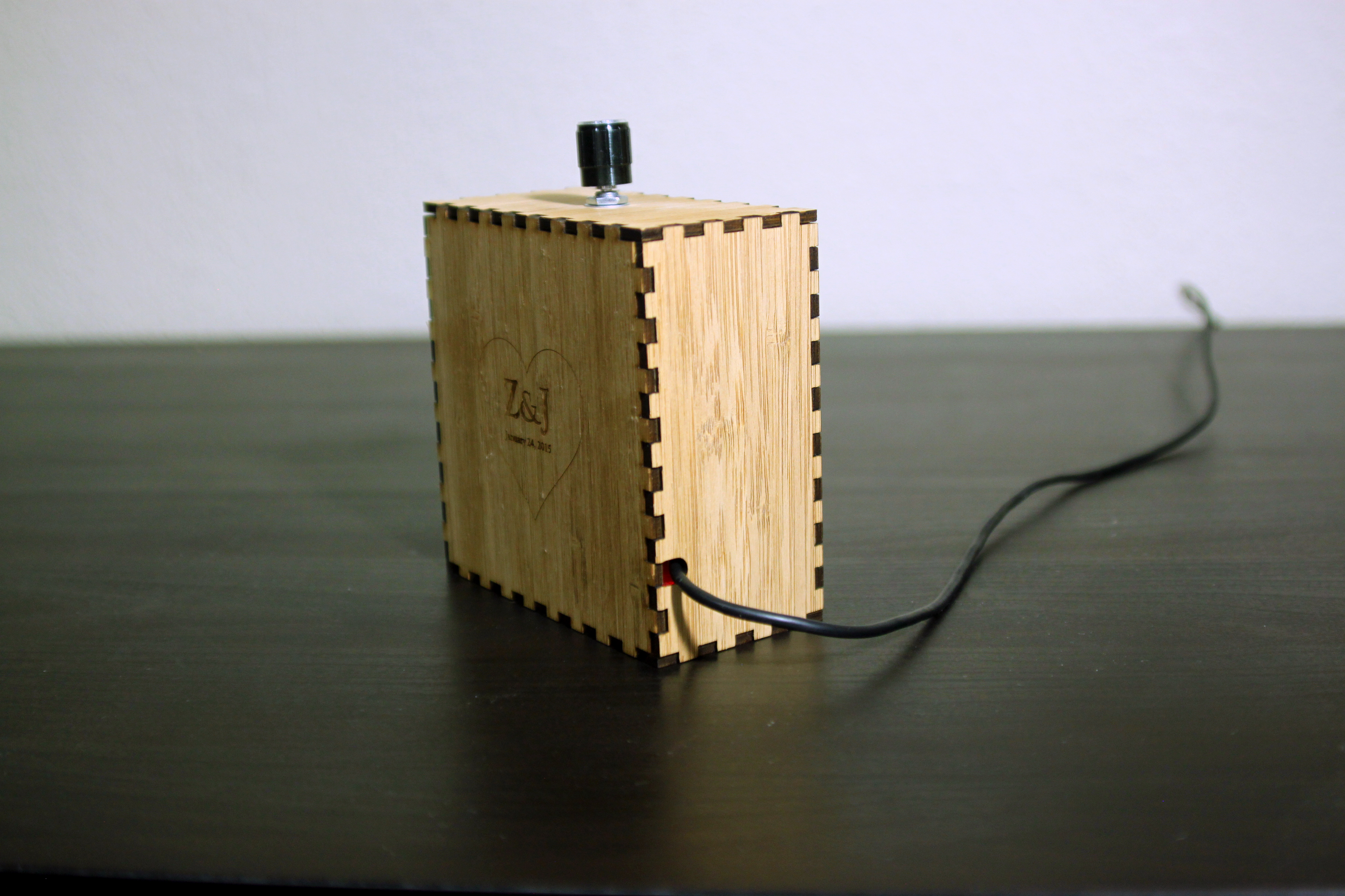
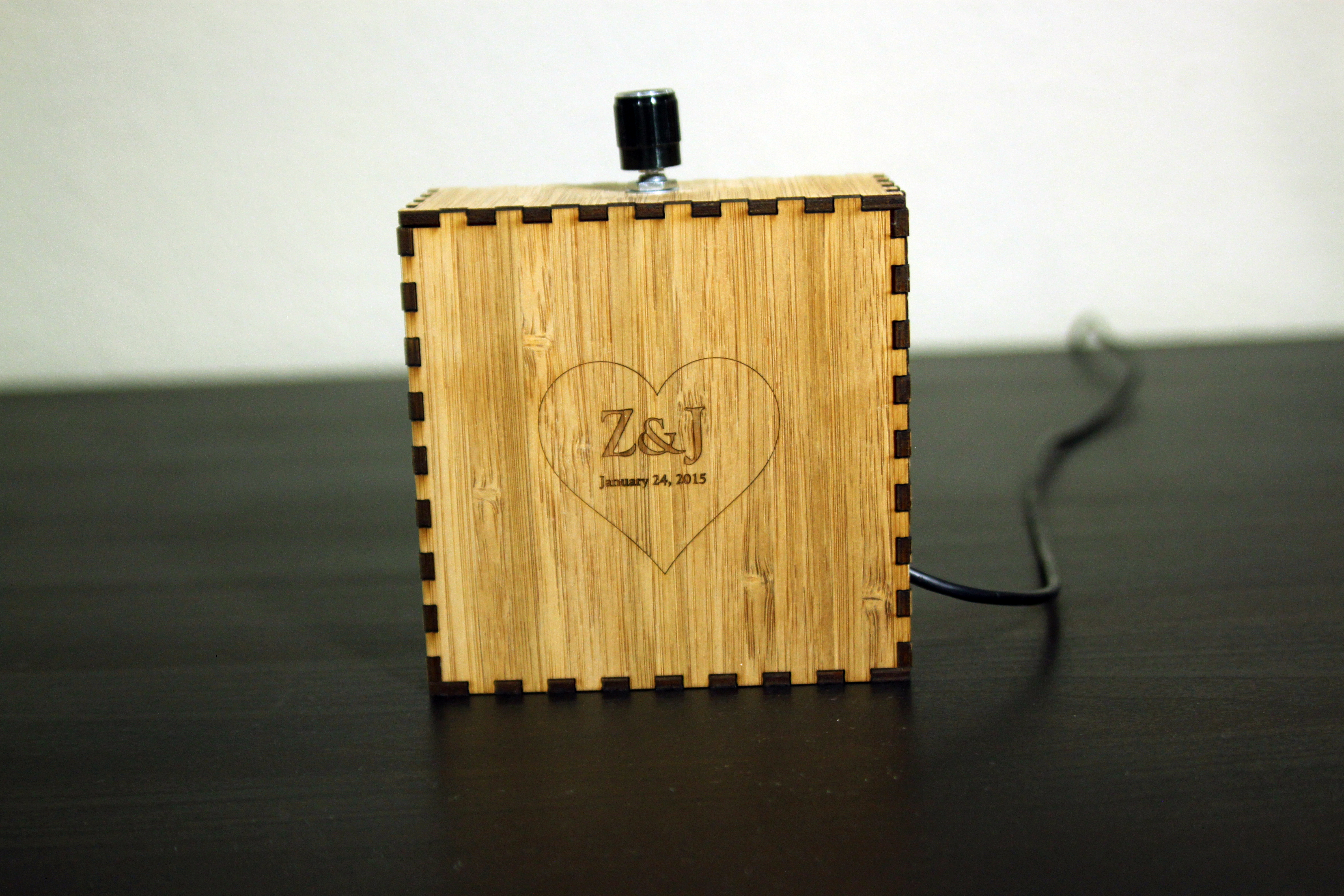
And what ended up being the winning concept, a laser-cut hinged design.

I decided to set my Kickstarter launch date as the same day as Houston Mini Maker Faire. This gave me a deadline, and I figured the Maker Faire would help me attract some backers.

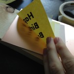
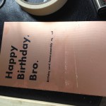
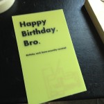
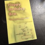
I made some business cards…

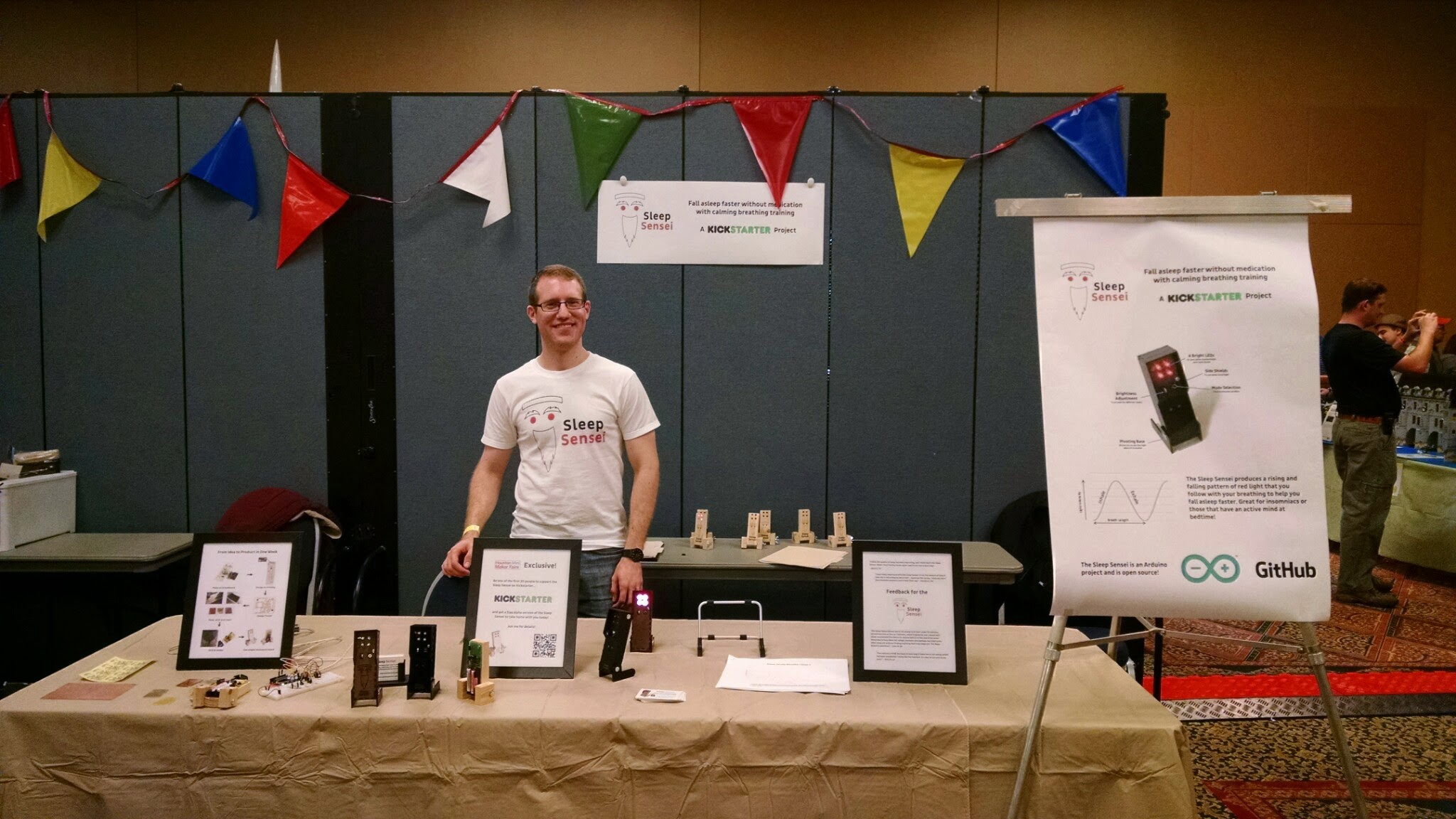
And set up a booth at the Maker Faire.

And I launched my Kickstarter page! However, it didn’t end up reaching the goal. I think several reasons factored in:

  • I made little effort outside of the Maker Faire to market the Sleep Sensei
  • I asked for way too much money. I had planned to have a vendor make and assemble all the PCBs, but this required a large volume of orders. I didn’t get anywhere close to what I needed.
  • The design was still rough around the edges

But, the failure of the first Kickstarter didn’t stop me, since Bay Area Maker Faire was just a few months away, and I had a couch to crash on in San Francisco. So I decided to improve the product and try again!

The Second Kickstarter

The New Strategy – Think Small

I figured that I still wouldn’t be able to get $25,000 for mass production, so I had to rethink how I would make the Sleep Sensei. I decided that if a reasonably small amount (less than 250) of Sleep Senseis were ordered, I would order the bare PCBs and solder the components myself. If quantities ordered exceeded these expectations, then the volume would be sufficient to put in a bulk order.

For example, I was quoted $8.27 per assembled PCB if only 100 were ordered, but the price went down to $3.57 each if I ordered 1000. The laser-cut bodies cost around $9 each shipped, and the mechanical components (knob, hinge) cost around $2. Adding in shipping, packaging, taxes, and Kickstarter fees, and the Sleep Sensei would sell at a loss at low quantities if I didn’t fabricate the boards myself!
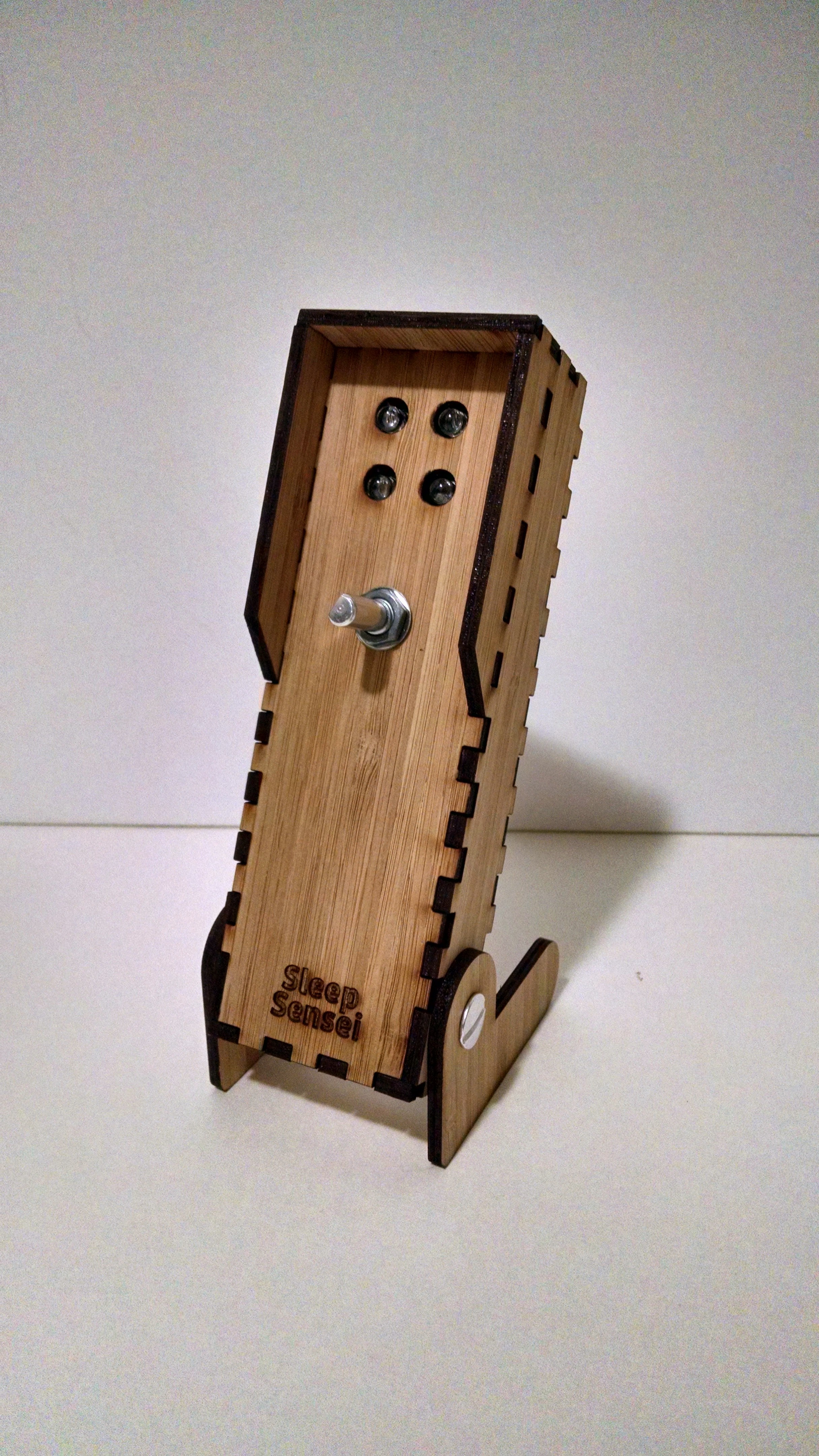
The New Design

For the second Kickstarter, I wanted to have a finished improved design for the Sleep Sensei. One bit of feedback I heard from several people was that the default breathing pattern wasn’t right for them. Some complained the breathing rate was too slow, while others couldn’t keep up.

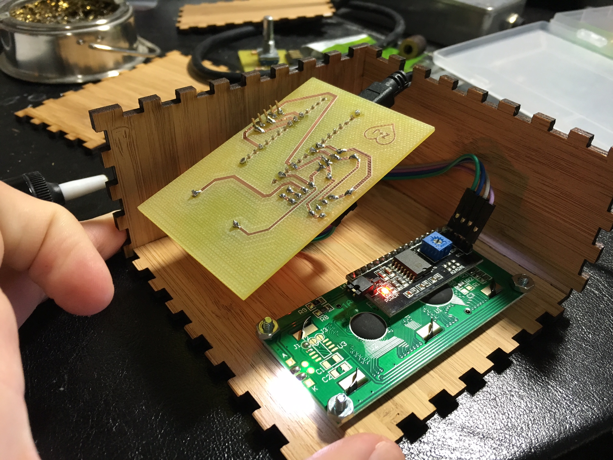
So, I wanted to allow the user to customize all aspects of the breathing pace: how long the breaths are at the start and end of the coaching session, and how long the session lasts. I had to rethink the design, since I wouldn’t be able to add all this functionality with just a button and a potentiometer. So, I switched up the design and opted for a rotary encoder with a built-in button.

This gave me 3 forms of digital input: two directions of the knob and a button press. With this, I modified the code to include “menus” the user could activate in order to change the settings, and I made someinstructional videos to clarify how the process is done.

I also stared making the Sleep Sensei out of bamboo, since I liked the look and found the price to be comparable to using plastic.

Updating the Kickstarter

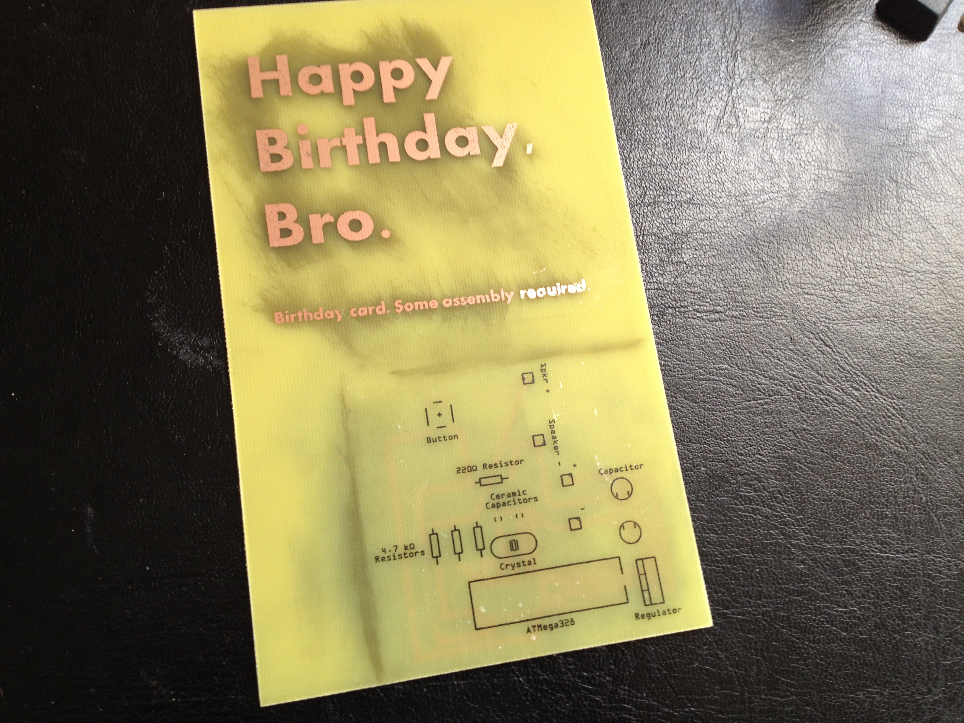
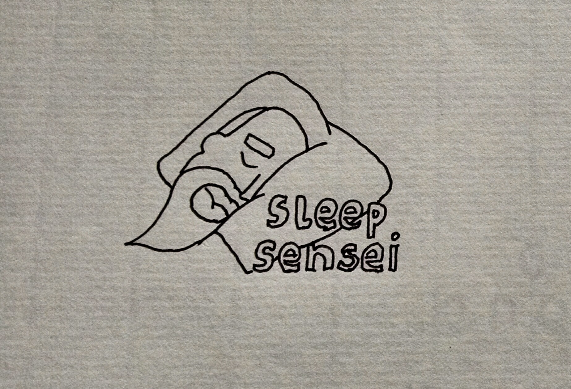
I also knew I needed a new logo and Kickstarter video. My girlfriend pitched in and came up with a sketch for a logo that I really liked:

I sent this over to a logo designer I found on Fiverr, and voila!


My girlfriend also helped me shoot the new video, with directing and writing help (and use of her Mac for some much-needed premium editing software).

I also found a reasonably priced professional product photographer on Fiverr, and had some nice shots of the Sleep Sensei taken.

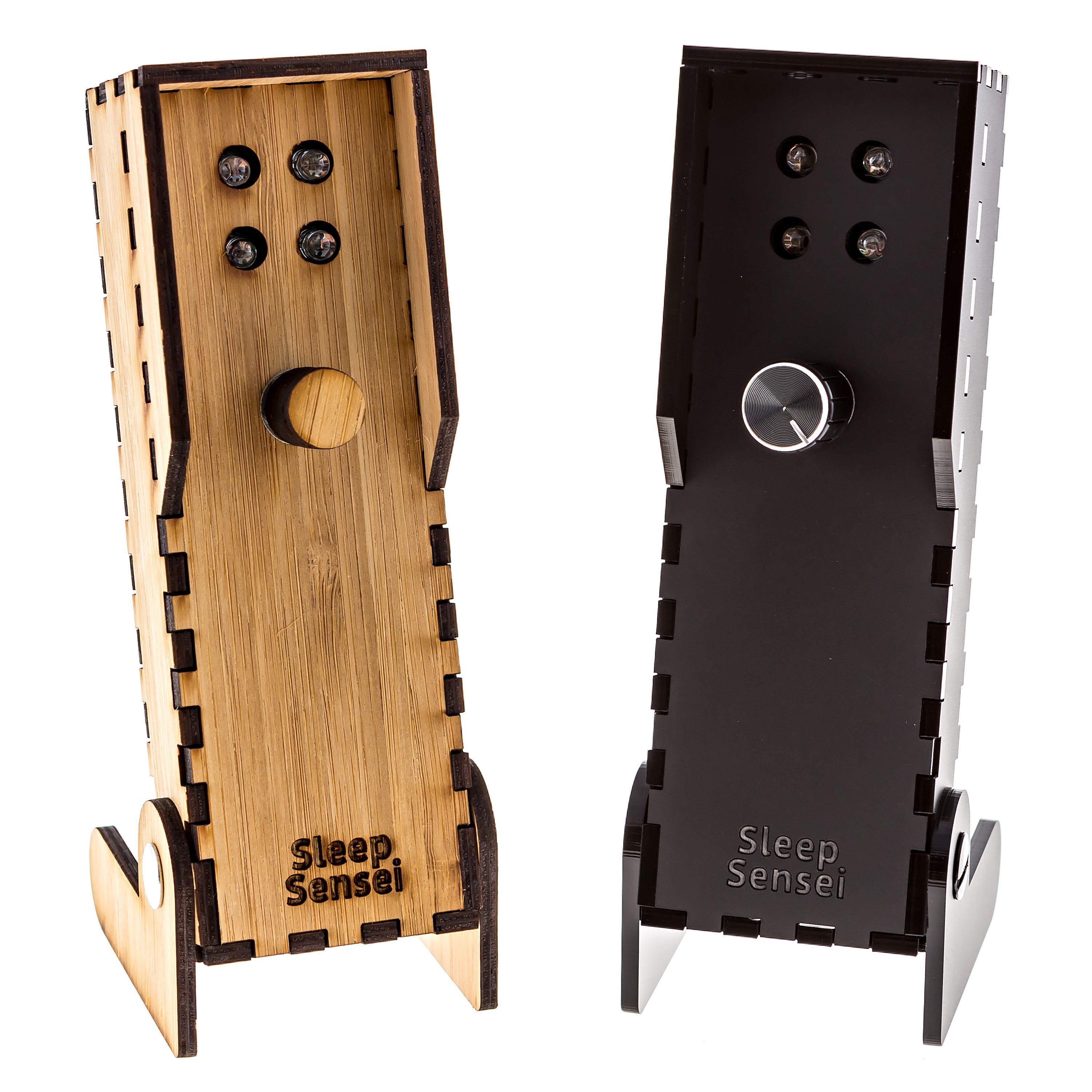
All in all, I wanted the new campaign to be more polished and professional, all while staying on a shoestring budget.

Marketing

This time, I wanted to be more proactive with the marketing of the Sleep Sensei, so I contacted Ponoko, the laser-cutting shop that produces the Sleep Sensei shell, and told them about the new Kickstarter. They were quite interested and ended up interviewing me and writing a post about it.

I also paid a couple of organizations that claim they will get you a bunch of backers through social media, but I did not get a single new backer as a result of their facebook posts and tweets. This seemed mainly because they sell the same service to hundreds of others, so your product is just one in a sea of many posts each day.

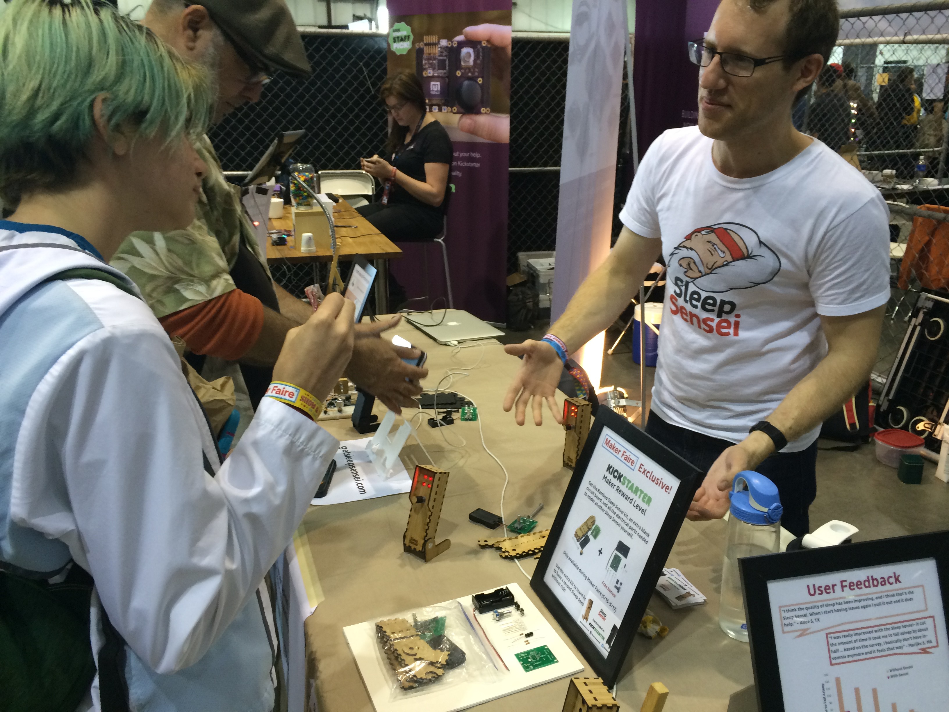
In the end, the Maker Faire ended up being the most valuable form of marketing, since I was able to show people the product and have them try it out in person. Most of my backers ended up coming out of the Bay Area, and I can assume that most of those backers were visitors to my Maker Faire booth.

After the Kickstarter

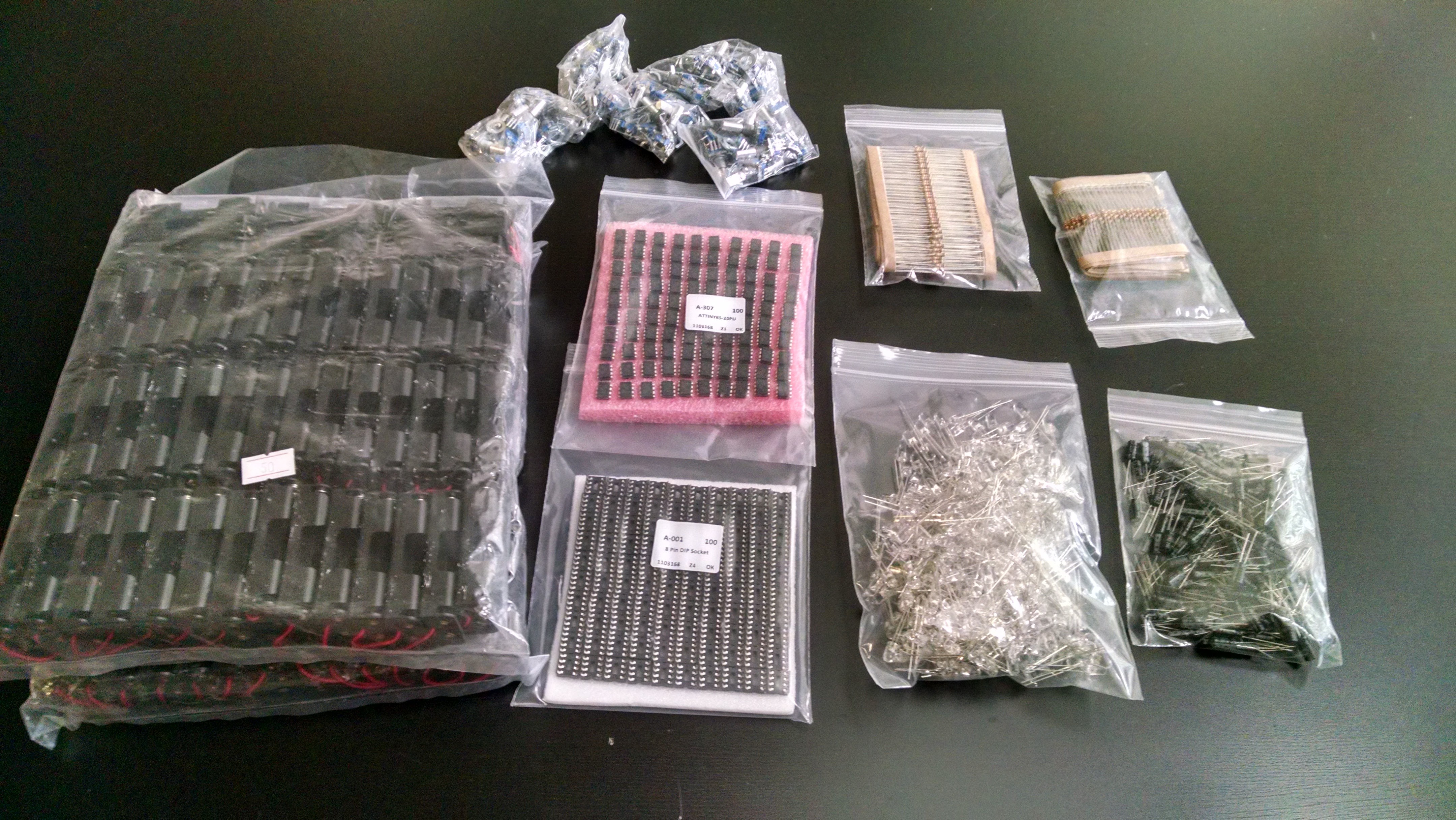
Once the Kickstarter was funded, I ordered all the things:

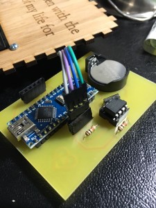
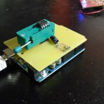
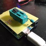
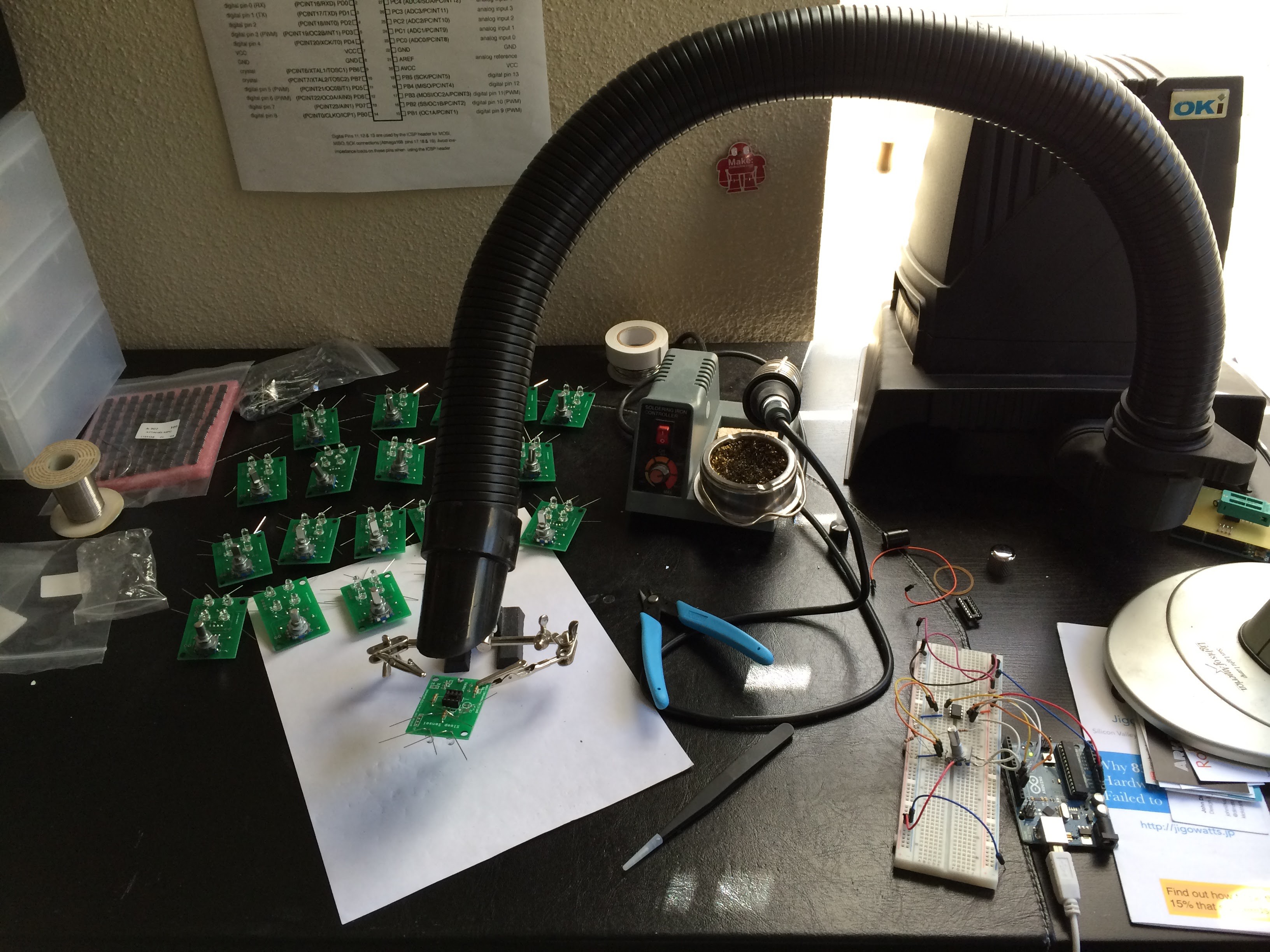
And got to work assembling the PCBs by hand:

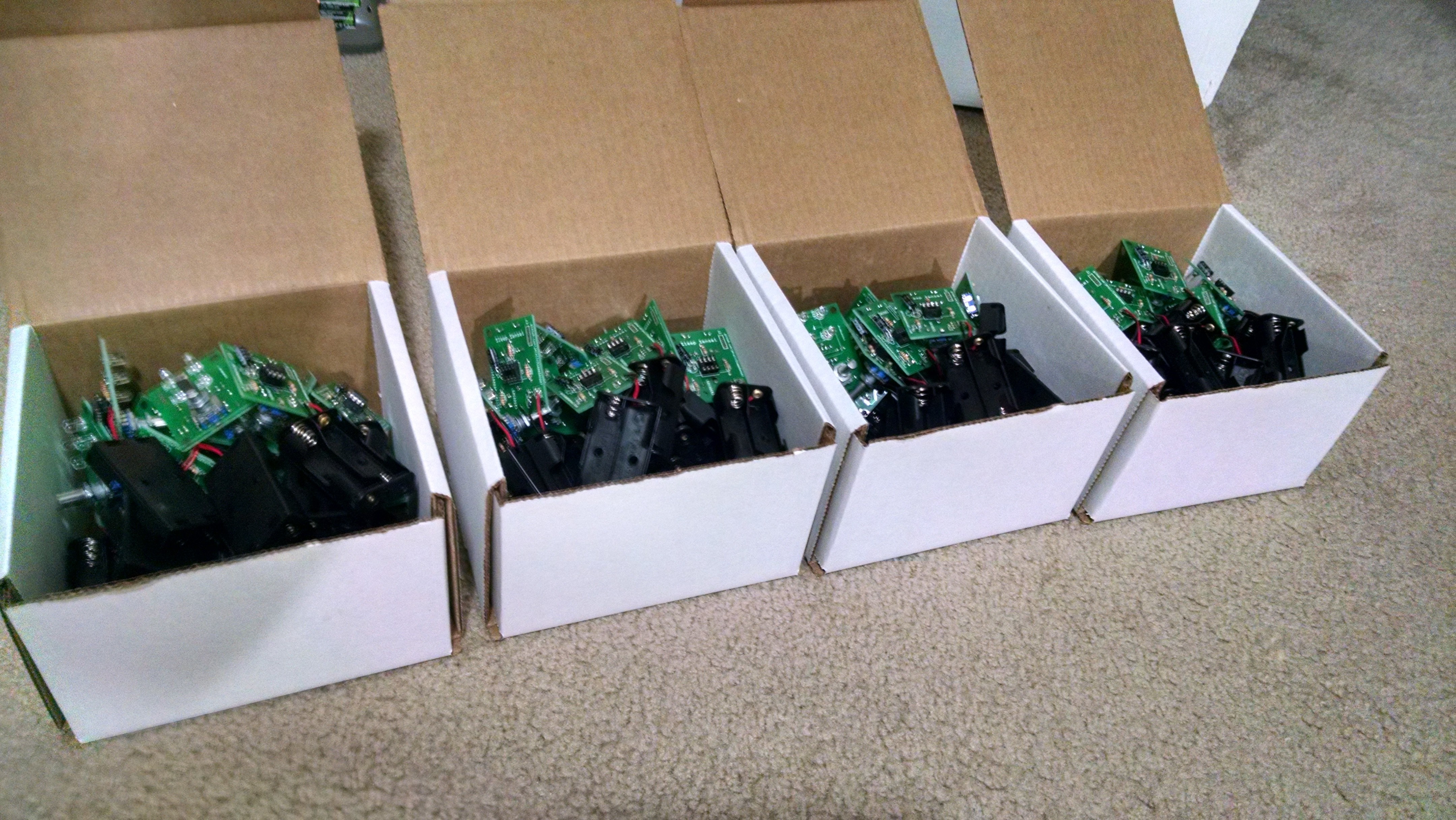
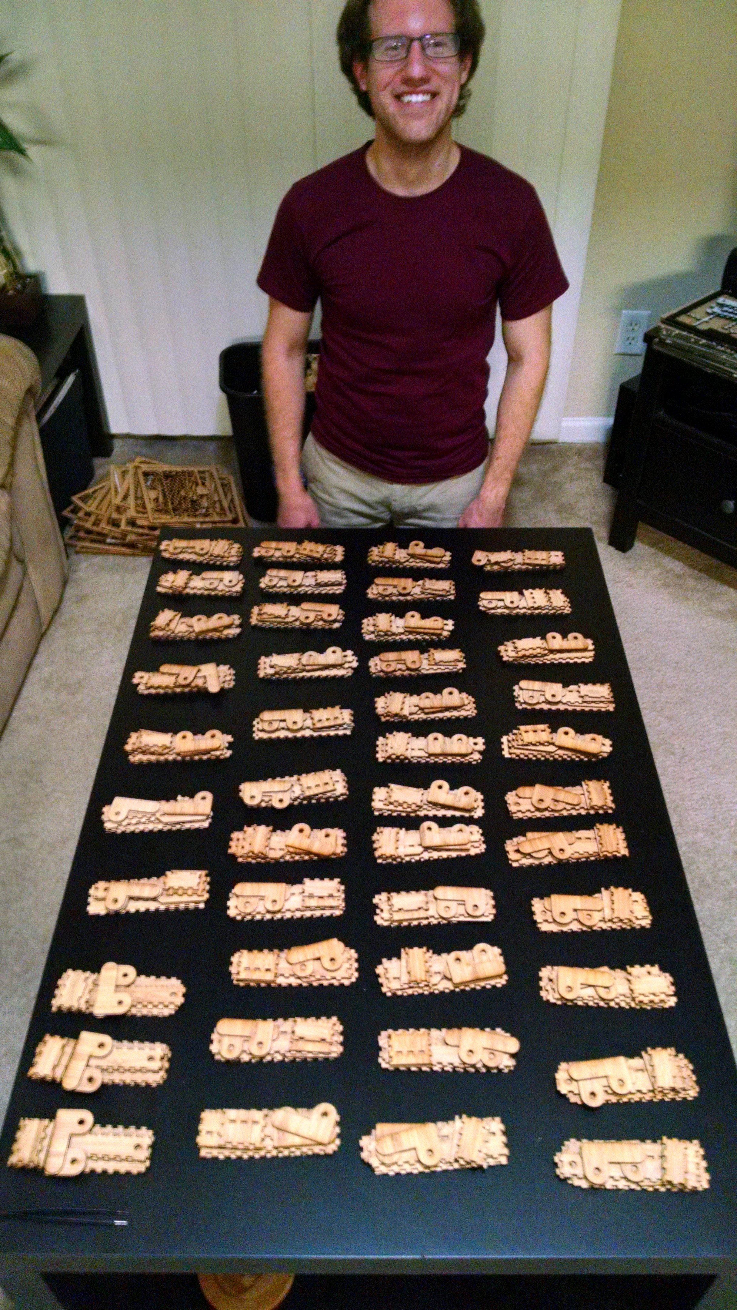
With my girlfriend’s help, we got all the lasercut components organized and ready to pack:

After a few weeks of assembling, packing, and shipping, all the Kickstarter rewards were out! I then did some research for a place to sell the Sleep Sensei going forward, and created a Tindie store.

Conclusion – You can’t do it alone

All in all, making the Sleep Sensei was a valuable experience. I got outside of my comfort zone to try to be a salesman, marketer, designer, video editor, photographer, web designer, electrical engineer, and mechanical designer. And I found that it was a lot of work!

I learned that if you want to be truly successful, you can’t do it all by yourself. For my first kickstarter, I tried to do it all on my own, and failed.

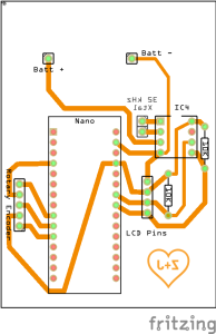
But the second time around, I had help from my girlfriend (logo designer, camerawoman, and great supporter), my brother Mark (editing of Kickstarter page, test subject, and Maker Faire booth hand), and paid help such as a professional photographer, a logo designer, and a music writer (for the video). I also was boosted by Ponoko’s newsletter piece about the new Kickstarter, and family and friends helped to share the Sleep Sensei on Facebook and Twitter. I even got some board design help from an electrical engineer friend at my workplace, and his feedback helped make the board smaller and more efficient.

I’m glad I was able to turn an idea of mine into an actual product, and I learned a lot along the way. Until the next great idea strikes, I’ll keep on tinkering!

Arduino Pong

I recreated the classic game Pong with an Arduino.

Arduino_Pong_Gif

During my Arduino training sessions, I tasked my students to come up with a cool project using Arduino and various sensors and other electronics I had collected. This was my project entry.

Check out the video demo to hear the beeps!

Arduino_Pong_bb

This project takes advantage of Adafruit’s SSD1306 OLED driver library and GFX Library.

For all the technical details, code, and schematic, check out the GitHub page.

ESP8266 and DHT22 – Log room temperature to a Google Sheet

I recently discovered the ESP8266: a low-cost board with a WiFi chip that also has a microcontroller that you can program with the Arduino IDE. For less than $2, this was something I had to try! So I decided that I wanted to use the ESP8266 with a DHT22 temperature and humidity sensor to log the temperature of my room in Google drive.

I wired and set it up using this guide:

https://learn.adafruit.com/esp8266-temperature-slash-humidity-webserver

But instead of a USB to serial cable, I used a UART TTL module to communicate with the board. Since the 2 x 4 pin design doesn’t lend itself to use in a breadboard, I used an adapter board.

The complete circuit is shown below:

IMG_2665 IMG_2666

Once I got the module reading temperature values from the sensor, I added code to send the data to Adafruit IO using the getting started guide:

https://learn.adafruit.com/adafruit-io/arduino

I then used an IFTTT recipe to add any new Adafruit IO values to a google sheet. This is what the values look like as they come in:

Screenshot 2016-03-10 21.42.11

And here is a plot of the temperatures over time. It looks a bit jagged since the temperature is being sent over as an integer, which is fine for my purposes.

Screenshot 2016-03-10 21.35.01

The Arduino IDE code can be found on my repository: https://github.com/jerwil/ESP8266_DHT_to_Adafruit

Interlocking Laser-cut Pieces – An Experiment in Design

When I was working on my Sleep Sensei project, I designed the housing out of interlocking parts to form the case.

IMG_4886

Initial Design

When designing the interlocking portions, I arbitrarily chose that the “notches” would be as wide as twice the material thickness and as tall as the material thickness to provide a good amount of interlocking without being excessive. For example, bamboo from Ponoko is available in 3mm thickness, so the notches are 3mm x 6mm (see diagram below).

Lasercut Notch Size Largetext

Click above image to enlarge.

This worked fairly well when the parts were glued together, but if not the whole thing would just fall apart. Since I was designing this product to be a kit to be assembled by my customers, I wanted to make it as easy as possible with no glue required.

Adding Nodes to the Design

When looking to improve the design, I came across this Ponoko article about adding “nodes” to interlocking laser-cut parts to provide a tighter interface. The concept I came up with was to add nodes to both the “male” and “female” notches to create an interference fit:

Node Diagram

The problem was, I didn’t know what dimensions to choose to make the fit tight enough without being too tight to assemble. I also had to make a design that is tolerant of inconsistencies in the laser cutting process. So I did a simple experiment to choose the best node size.

Node Sizing Experiment

I decided to make the width of the nodes 1/2 of the material’s thickness, or 1.5 mm in the case of the bamboo I was using. But I didn’t know how “tall” to make the nodes.

Node Dimensions Diagram

So I used AutoCAD to create a test piece that would test both the 90 degree connections of the corners as well as inserting into a series of holes (such as on the sides of the Sleep Sensei). The test pieces could be inserted into each other to test different combinations of node sizes. A sample test piece is shown below:

Indiviadual Test Piece

I created a series of test pieces with varying node heights, and I made 4 of each piece to account for variability in manufacturing. I etched each part with its node height so I could keep track:

All Node pieces

For example, the below test piece has a node that is 0.03 mm high:

Node Dimensions

When the parts came in, I tried all the combinations of node sizes, and I found that the fit was best with 0.05 mm nodes on both pieces. So I modified the Sleep Sensei design to include this node size:

New Sensei Design

Notches Up Close

And the design works quite well! If you check out the assembly video, you’ll see that the parts snap together quite nicely.

I used the same node size for my valentine’s day count-up box, and that also worked out quite well. The parts work like lego pieces: firmly snapped together but easy to take apart if needed.

Count up Box – A Valentine’s Day Gift

The Count up Box

Front

For Valentine’s day 2016, I decided to make a device to count up how much time has passed since my girlfriend and I first met.

What I came up with is a fairly simple design utilizing an Arduino nano, a real time clock, an LCD screen, and a rotary encoder.

As I have some decent experience with laser cutting from my Sleep Sensei project, I decided to have the project laser cut.

Demo Video

Photos

Side Back IMG_2620

Technical Details

The knob on the top of the box is attached to a rotary encoder with a built-in momentary switch. I use this to change the unit display on screen and allow the user to adjust the date and time.

Getting the screen working was the largest challenge of this project. It is a 1602 16×2 HD44780 screen from aliexpress, and it uses an I2C converter to allow me to send it commands via an I2C interface, simplifying the wiring significantly. However, it was hard to find the correct arduino library to interface with it. After much searching and testing, the LiquidCrystal_I2C library was the one that worked for me. The documentation for this library isn’t the greatest, but the commands can be found in the LiquidCrystal_I2C.h file.

The whole project is powered directly from the Arduino nano. This allows for easy code swapping and prototyping since the power cable is also the communications cable, and it simplifies the design of the circuit board since I can use the nano’s on-board power supply.

The code, lasercutting files, board schematics, parts list, and more details can be found on my GitHub:

https://github.com/jerwil/Count_Up_Time

Circuit Board Design

Count Up Box Schematic Production_pcb  IMG_2618

The circuit board was designed in Fritzing, and the design files can be found on the GitHub page.

Heart PCB – A Valentine’s Day Gift

Heart Card Animation Compress

I started dating my girlfriend at a pretty awkward time. Just three weeks into dating her, Valentine’s day reared it head, and I wasn’t sure what kind of gift I should give her, if any. I mean, it had only been three weeks!

The Idea

At the time, my workplace just got a new circuit board mill, and I was excited to make new boards with it. So I came up with a plan that was low on cost, but would still produce an awesome gift (to those nerdy enough to appreciate it). I had already made a “camera show” device that had a series of LEDs that lit up in a pattern, so the idea was to translate that design into a heart-shaped “card” milled out of a copper board, complete with her name etched on the front.

The Execution

Since the basic board layout and Arduino code were already available, I just had to figure out how to translate it to a heart-shaped design. I followed the Fritzing guide for making a custom board shape and found a .svg heart shape online to use as the board outline. I used Inkscape to make the modifications required to import the file, and moved the LEDs around to follow the outline of the heart. I also swapped the AA battery holder for a coin cell battery holder to make it more “card-like.”

Camera show to heart

I etched her name by adding a machining process step in the PCB mill software, CircuitPro. Although I did get her name a bit wrong by only including the first portion of it! Hey, remember that we were only dating for three weeks at the time.

The Gifting

I’m happy to say that she loved the card when I gave it to her, and she even framed it to put on display!

Heart Card in Frame

And as a followup after posting my count up box valentine’s day project, 13 months in and she still has it on display!

More Information

You can find the board design Fritzing file and the .svg file used on my GitHub page. The Arduino code was pulled straight from my “camera show” project repository.

View of the back of the board:

IMG_7997

ATtiny85 Flashing Shield

This was a quick and simple project mainly intended to test creation of a dual-sided board on a PCB mill I recently acquired access to. It will also make it easier and quicker to flash programs onto an ATtiny85, especially when flashing many of them at a time.

I followed this guide to determine which pins should be connected to what in order to flash a program onto an ATtiny85. Photos of the completed board can be seen below:

The board was tested, and it works quite well. It certainly cleans up a bunch of wires!

The board design in Frizting:

ATtiny85 Flashing Shield_bb ATtiny85 Flashing Shield

As usual, the schematic can be found on my github.

ATMega328 Flashing Sheild

About a year ago when I first started with Arduino, I learned that projects can be taken off the arduino to stand alone on a breadboard or finished PCB. I also discovered that it was significantly cheaper and easier to buy an ATMega328 chip without a bootloader and burn the bootloader yourself instead of buying one with the bootloader preloaded.

I followed a guide from 3guys1laser.com to get everything I needed to burn a bootloader onto a breadboard:

Flashing Sheild Construction

I then decided that it would be inconvenient to have to bring out a breadboard and wire everything up every time I buy a new ATMega chip. Thus, I created a “shield” of sorts that would plug directly into an Arduino.

I used a ZIF socket to make taking ATMega chips in and out a breeze. And since I’ve been experimenting with photography and animation lately, here is an animation of the shield in operation, burning a bootloader onto an ATMega328:

Flasing-Shield-Animation

I do not have any code or schematic for this project since it was all done on-the-fly (and before I knew about github and Fritzting!). See the guide at 3guys1laser for details on how to make your own!

Arduino Simon – Final Version

My first ever Arduino project has been through a series of upgrades as I’ve learned new techniques for making electrical circuits. It all started out on a breadboard. I then learned how to break free from the Arduino and make an independent project. Next, I created a more permanent version of my Simon game on a pre-perforated board. And now my Simon game is here in its final form, etched onto a copper board:

Simon Etched Side View

I am pretty proud of how this turned out; I think it looks a lot neater and more professional than my previous iterations of the game. I was happy to go back to my first project and give it a final touch with an etched design.

You can see me losing at the game here:

Here are some additional photos of the project:

As usual, you can get the code and schematic on my github: https://github.com/jerwil/Simon_Etch

Check out the evolution of the project:

Simon Breadboard

Breadboard version

image_2

Perf board version


Musical Arduino-based Birthday Card

This year, I wanted to make my brother something special for his birthday. Instead of just sending him some store-bought Halmark card, I decided to make him one myself! Using my new-found Arduino skills, I set out to create a birthday card that would inspire him to learn to solder. The end result is the educational musical birthday card:

Birthday_Card_Photo

This was my first ever two-sided PCB, although it doesn’t really take advantage of any communication between the two sides of the board. The two-sided board is just used such that the writing on the card and the circuit traces can be on opposite sides for aesthetics.

With the card, I included a kit of parts as well as a link to instructions to assemble the card: https://www.jeremyadamwilson.com/birthday-card-instructions/

I made the “silkscreen” portion (the black text and images) by toner transfer after I etched and clean up all the copper traces. This proved to be a very effective and simple method of adding text and images to a board for a more complete and professional look.

A quick making-of gallery:

My brother soldered the parts on, and he sent me a photo of the completed birthday card, which works!

birthday card complete

A demo of the circuit working can be seen here:

http://www.youtube.com/watch?v=ASfwomKhCUE

As usual, all of the code and a schematic are posted on github:

https://github.com/jerwil/Birthday_Card

Special thanks to http://miduino.net/ for providing an easy way to turn a midi file into arduino code.