When I was working on my Sleep Sensei project, I designed the housing out of interlocking parts to form the case.
Initial Design
When designing the interlocking portions, I arbitrarily chose that the “notches” would be as wide as twice the material thickness and as tall as the material thickness to provide a good amount of interlocking without being excessive. For example, bamboo from Ponoko is available in 3mm thickness, so the notches are 3mm x 6mm (see diagram below).
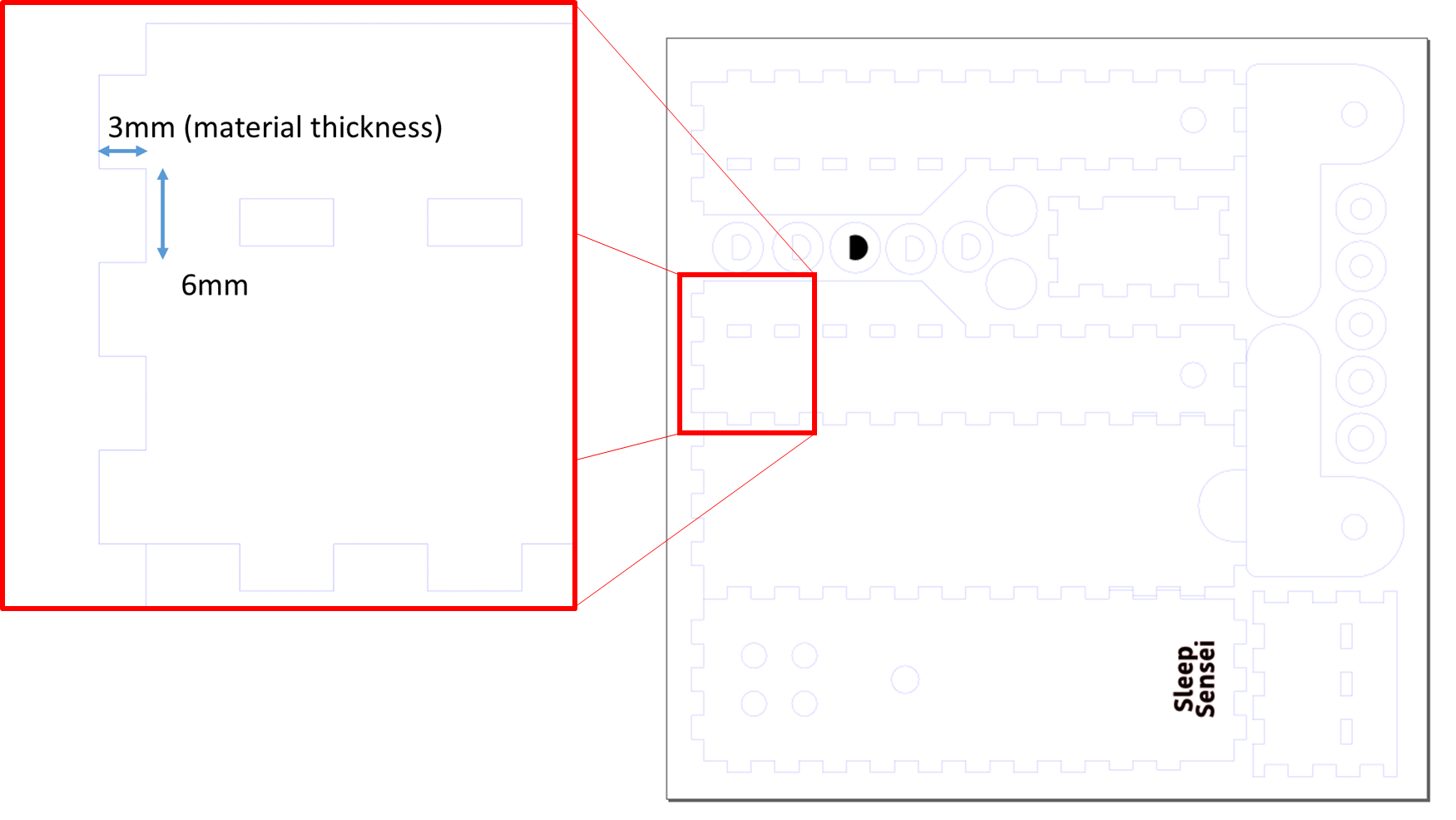
Click above image to enlarge.
This worked fairly well when the parts were glued together, but if not the whole thing would just fall apart. Since I was designing this product to be a kit to be assembled by my customers, I wanted to make it as easy as possible with no glue required.
Adding Nodes to the Design
When looking to improve the design, I came across this Ponoko article about adding “nodes” to interlocking laser-cut parts to provide a tighter interface. The concept I came up with was to add nodes to both the “male” and “female” notches to create an interference fit:
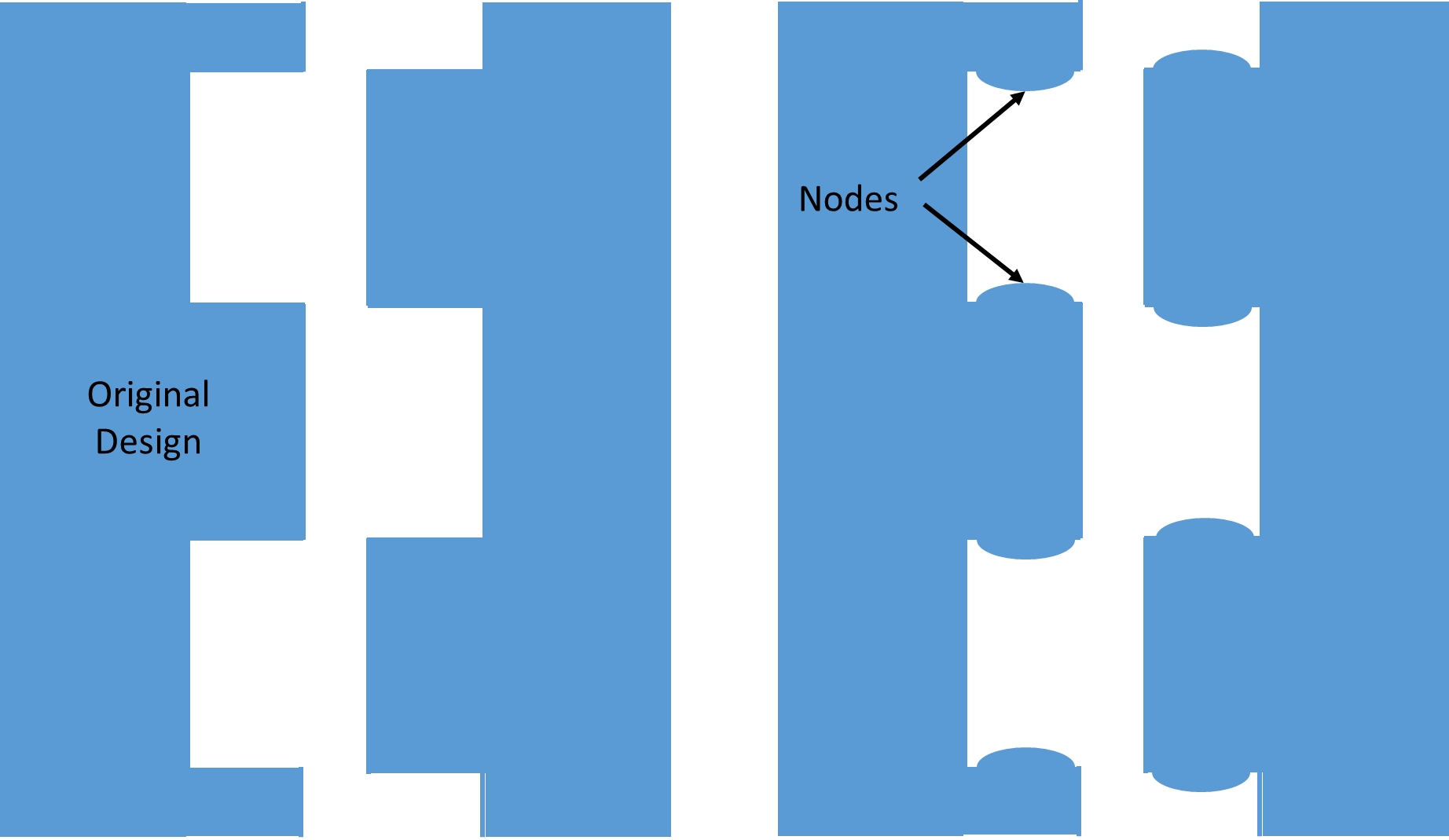
The problem was, I didn’t know what dimensions to choose to make the fit tight enough without being too tight to assemble. I also had to make a design that is tolerant of inconsistencies in the laser cutting process. So I did a simple experiment to choose the best node size.
Node Sizing Experiment
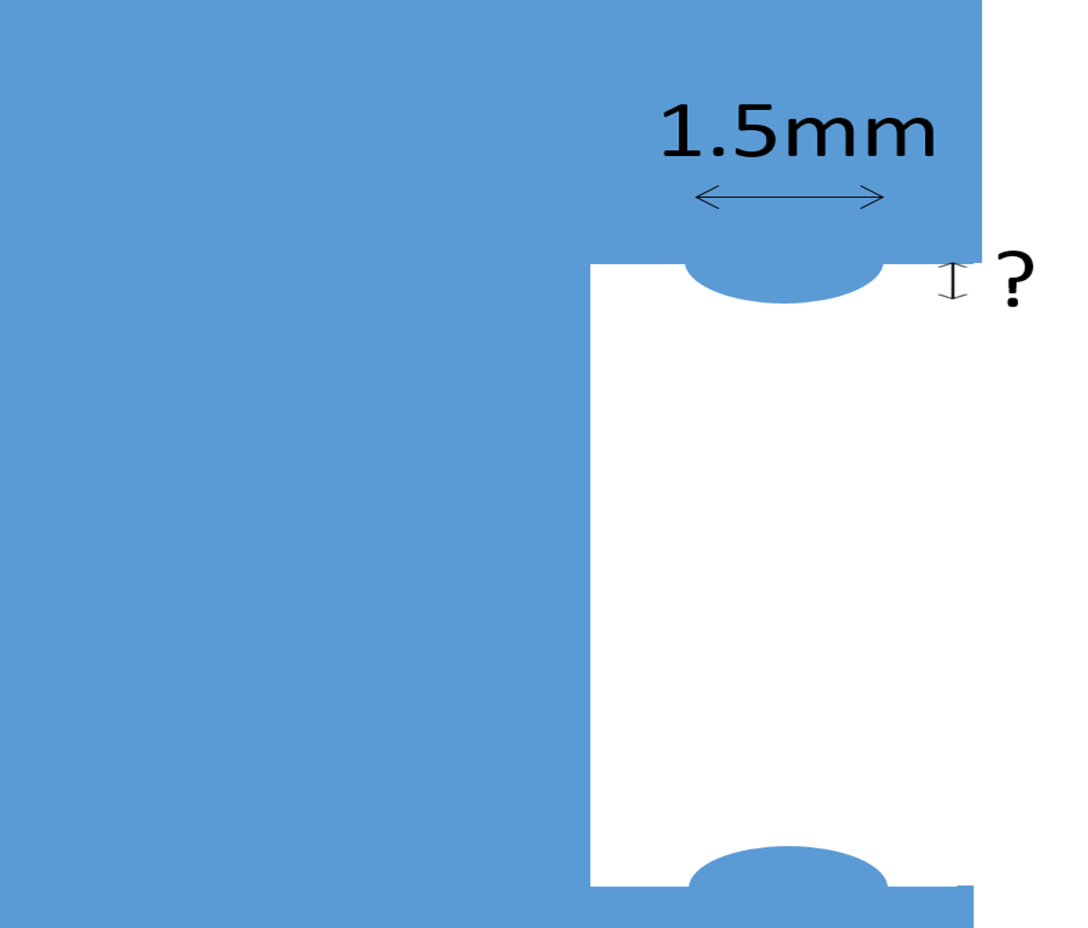
I decided to make the width of the nodes 1/2 of the material’s thickness, or 1.5 mm in the case of the bamboo I was using. But I didn’t know how “tall” to make the nodes.
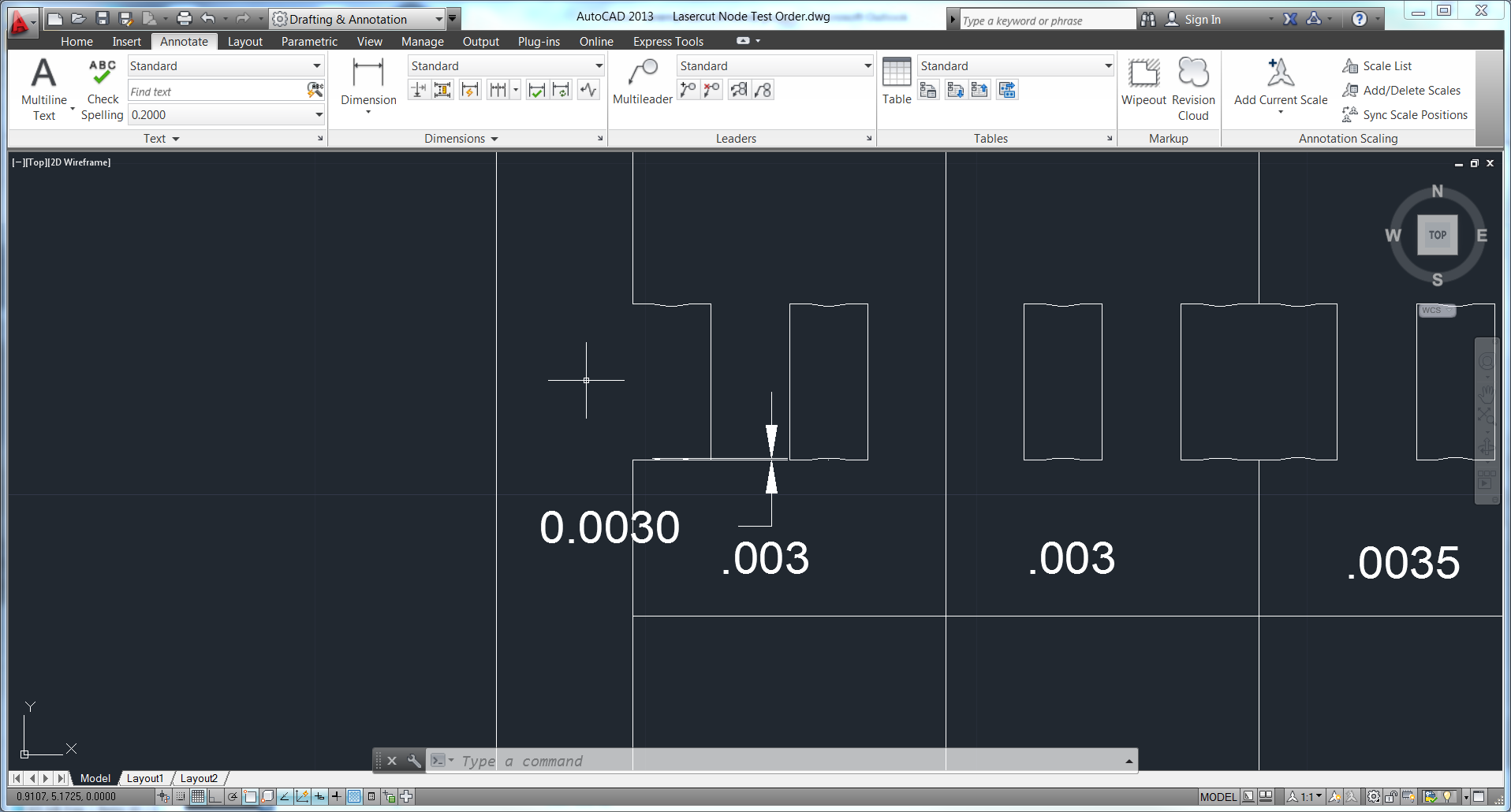
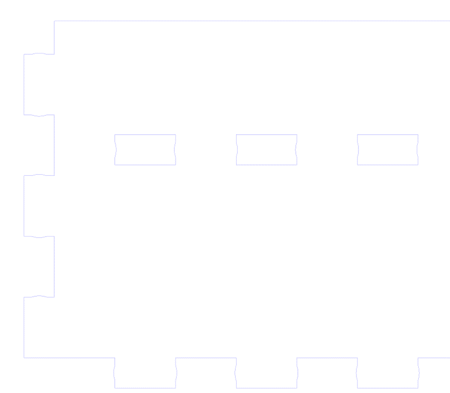
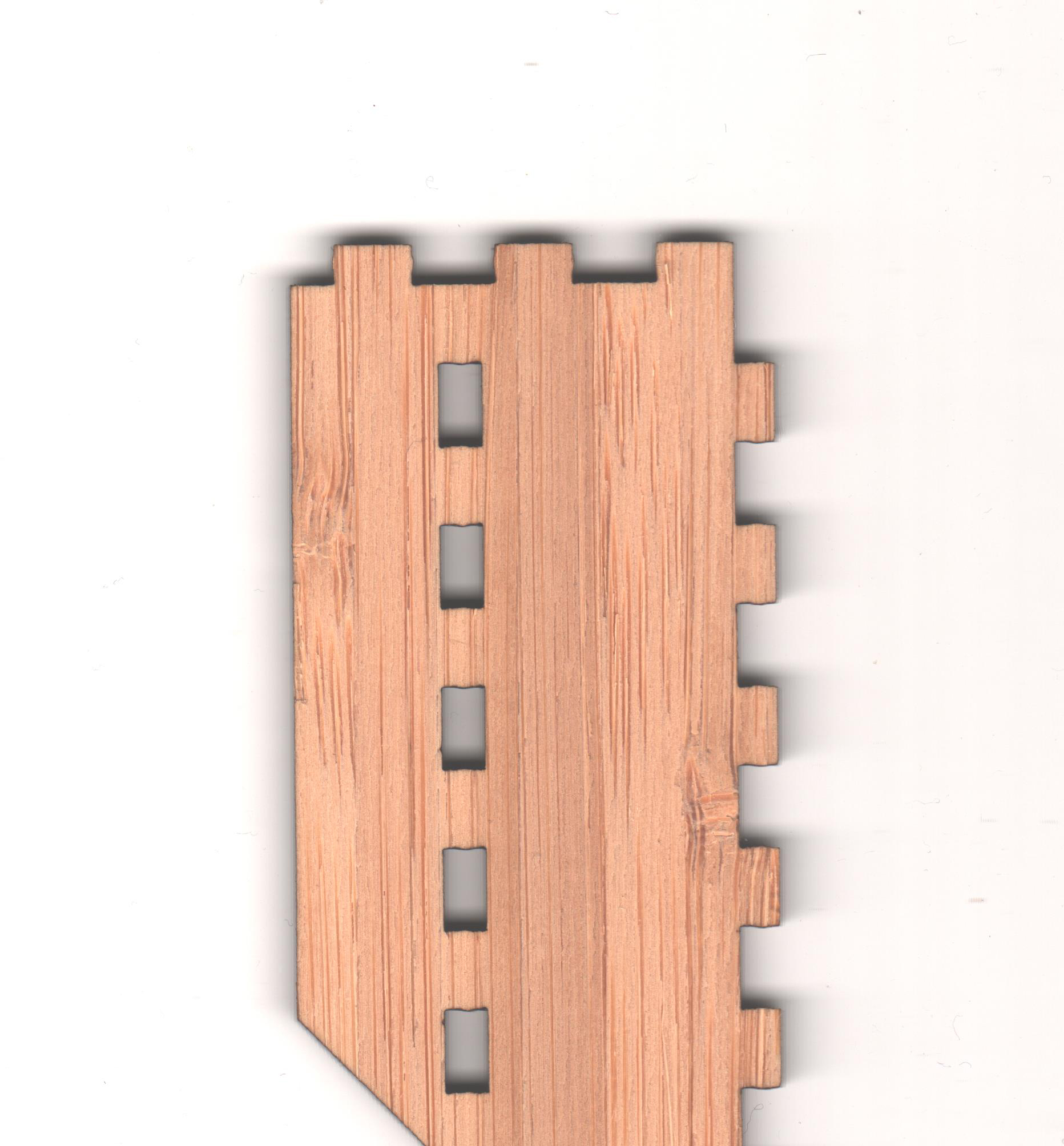
So I used AutoCAD to create a test piece that would test both the 90 degree connections of the corners as well as inserting into a series of holes (such as on the sides of the Sleep Sensei). The test pieces could be inserted into each other to test different combinations of node sizes. A sample test piece is shown below:
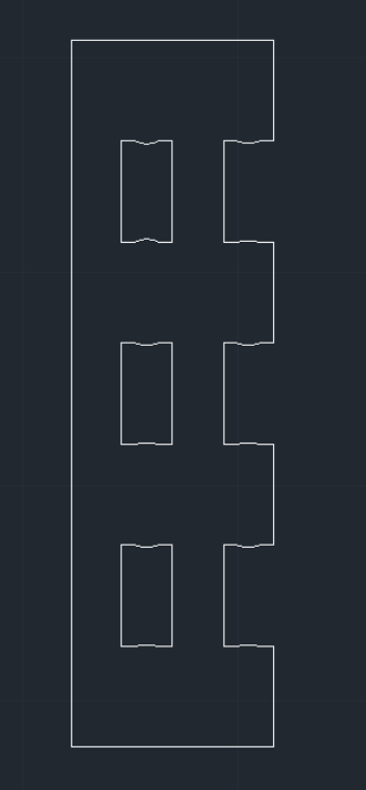
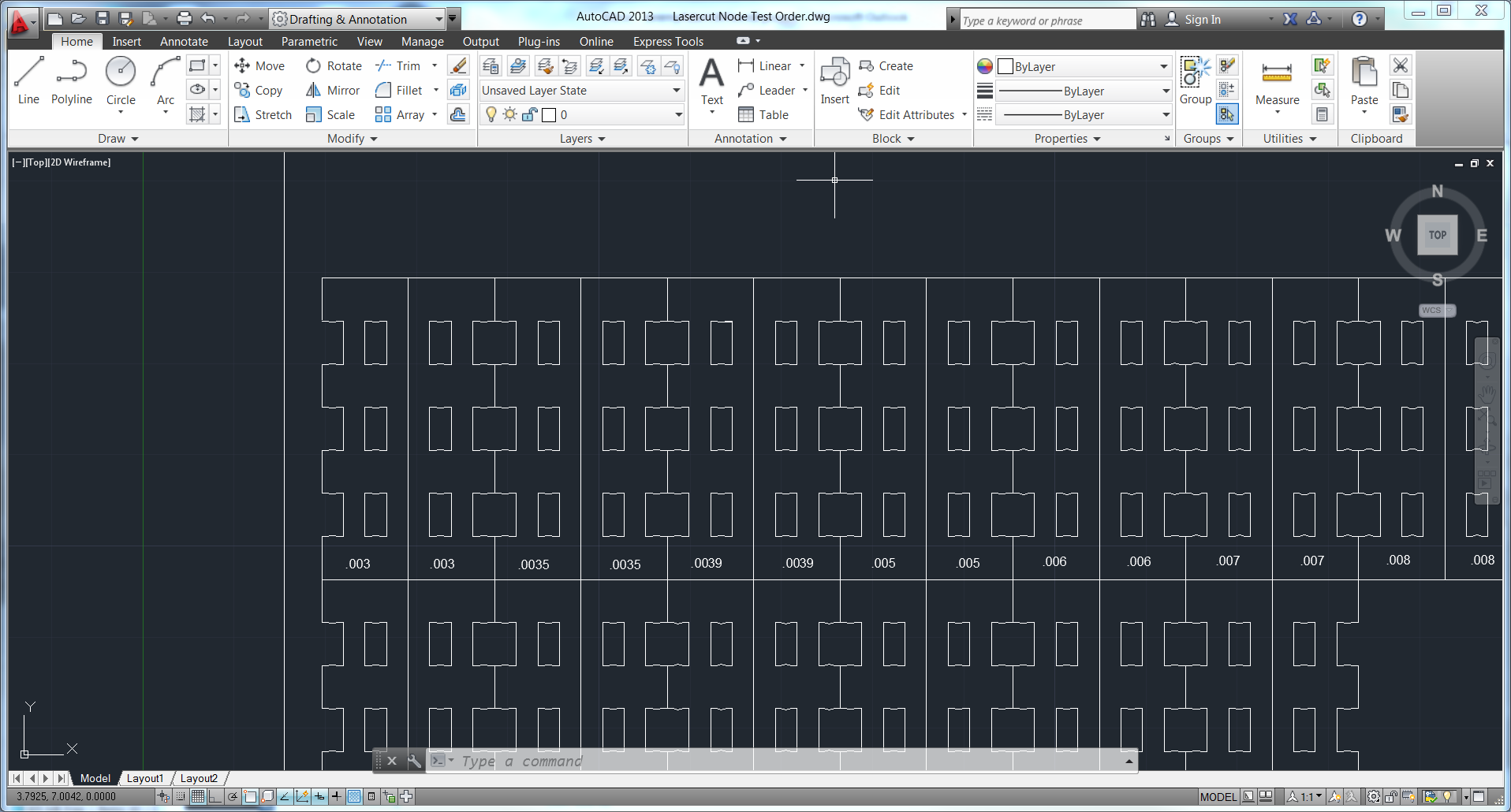
I created a series of test pieces with varying node heights, and I made 4 of each piece to account for variability in manufacturing. I etched each part with its node height so I could keep track:
For example, the below test piece has a node that is 0.03 mm high:
When the parts came in, I tried all the combinations of node sizes, and I found that the fit was best with 0.05 mm nodes on both pieces. So I modified the Sleep Sensei design to include this node size:
And the design works quite well! If you check out the assembly video, you’ll see that the parts snap together quite nicely.
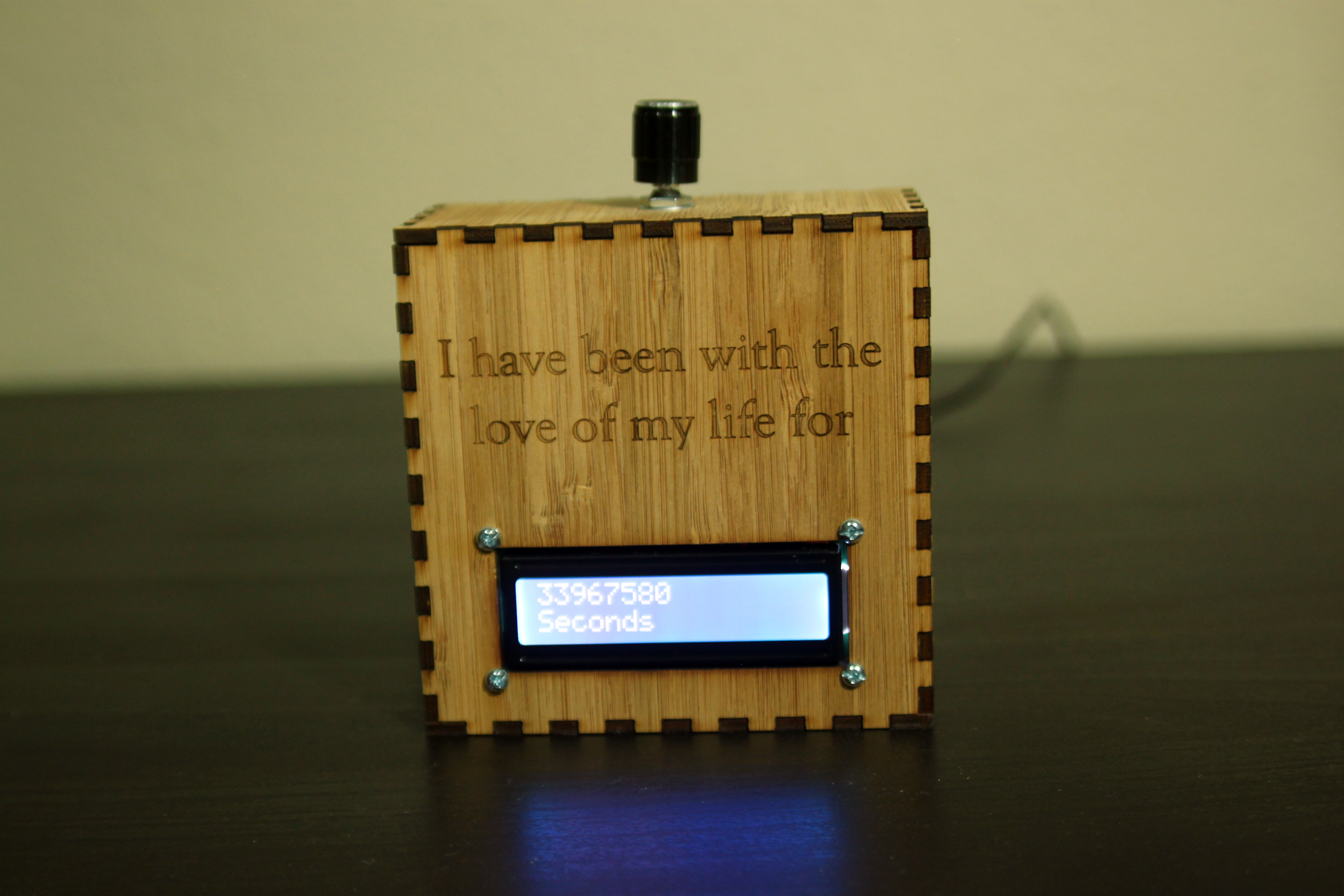
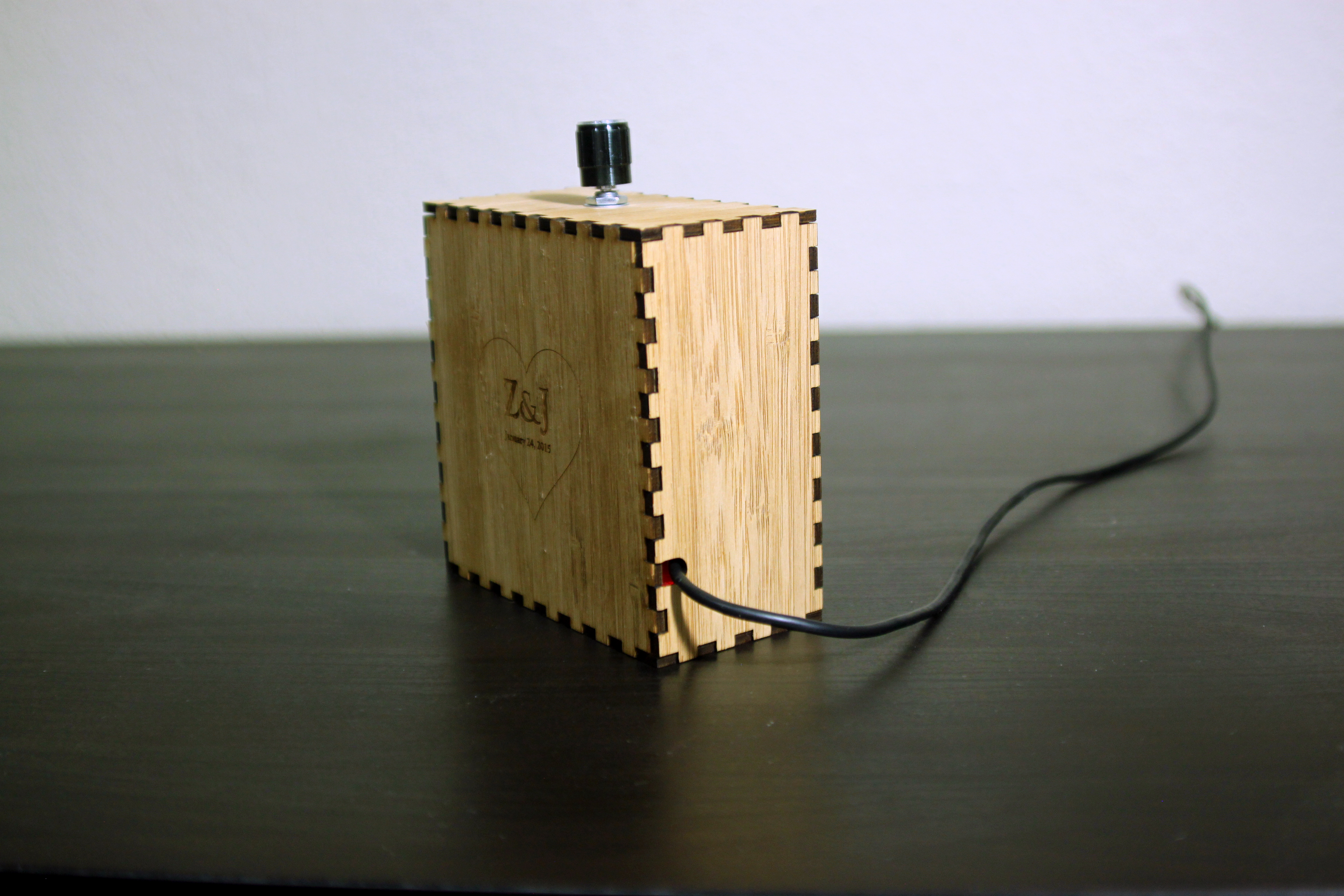
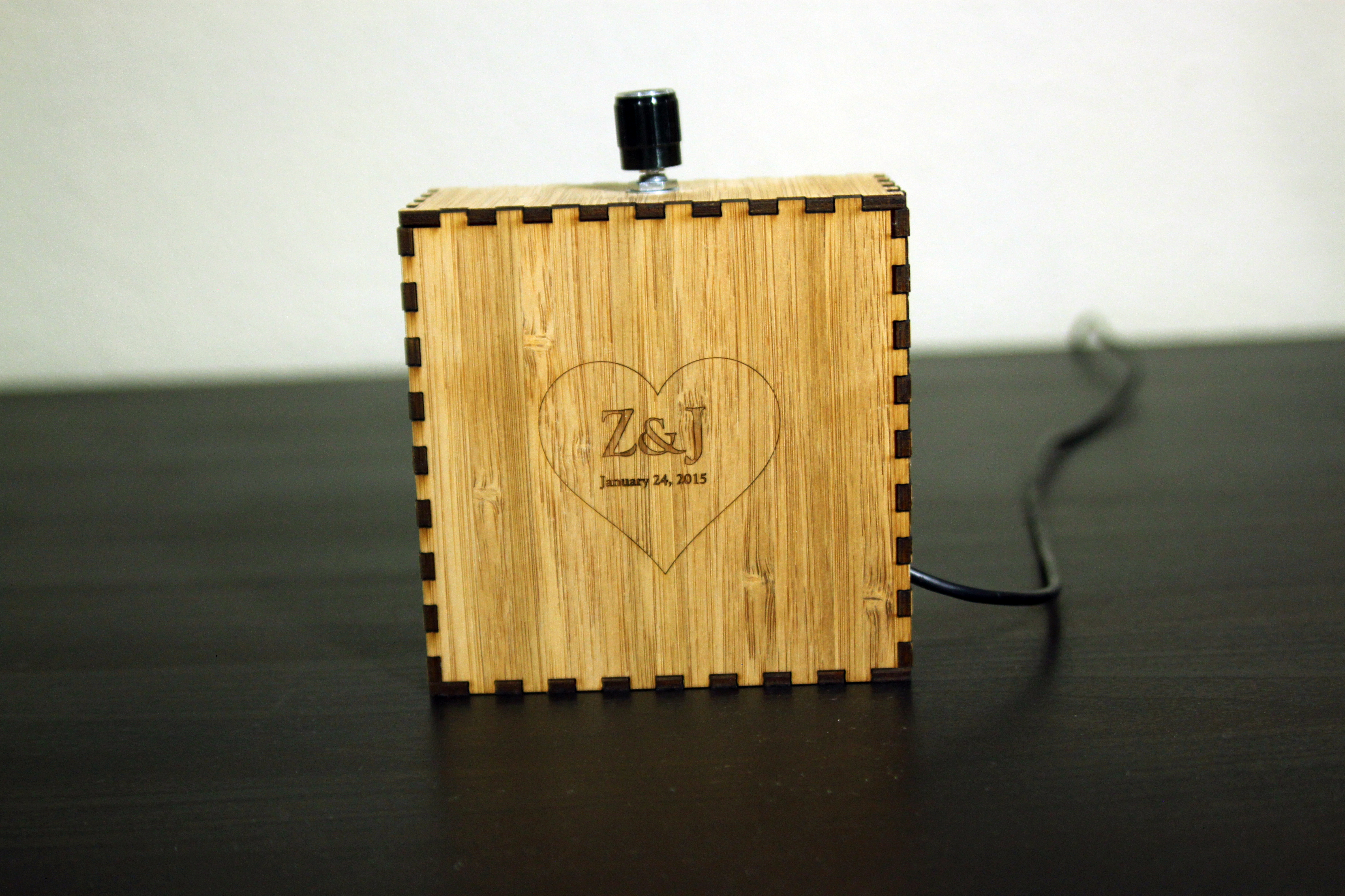
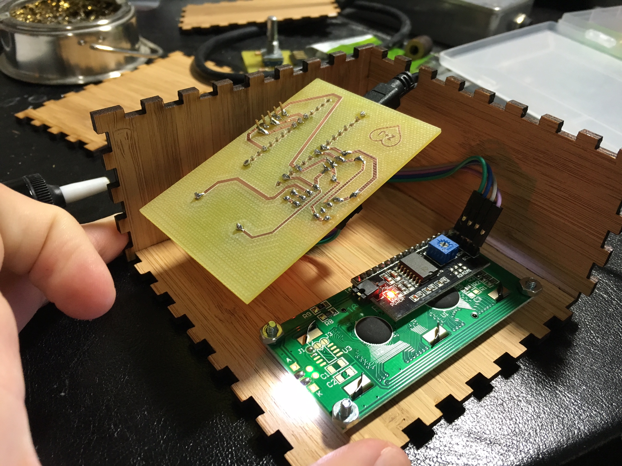
I used the same node size for my valentine’s day count-up box, and that also worked out quite well. The parts work like lego pieces: firmly snapped together but easy to take apart if needed.