
Hey bro,
Happy Birthday! I’ve made you a birthday card that should hopefully teach you how to solder. I estimate it will take about 1 hour for you to complete. Once you solder it all together and put in your 9V battery, it will play a song. Below is a description of all the parts that I’ve included:
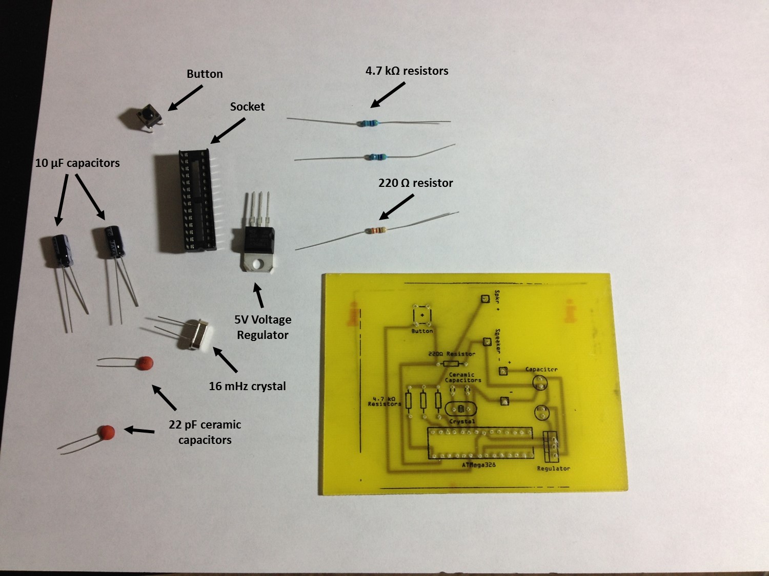
- 10 μF electrolytic capacitors: These go between ground and power for the input power of 9V as well as between the ground and power for the board power of 5V. They help to keep the power smooth to prevent spikes. The white stripes indicate which leg is ground (-). On the board, the ground pin is indicated by two lines on either side of the hole. These are the only components that you’ll be dealing with that have a required orientation.
- Button: It’s a button. You push it, and it electrically connects all 4 pins together. By default the left two pins are always connected together, and the same goes for the right two pins.
- Socket: A 28-pin I soldered on for you already. This allows you to remove the ATMega328 and protects its pins from the heat of soldering.
- 4.7 kΩ resistors: These are used to reduce the current going to the speaker, which lowers the volume output. There are 3 for the three available channels of audio. For your card as-is you technically only need the right 2, but if you wanted to reprogram the card with a more complex song, you could use all 3 channels.
- 220 Ω resistor: This is what is known as a pull-down resistor. It ensures that the input pin sees pure ground when the button is not pressed. Without this, the pin would be “floating”, and any interference could cause a false HIGH reading. See more info here: http://arduino.cc/en/tutorial/button
- 5V voltage regulator: Turns an input voltage of 6-24 volts and turns it into 5V, which is what the ATMega likes.
- 16 mHz crystal: This is used by the ATMega328 to keep precise time. This is important for this application to keep the audio tones consistent. This crystal’s resonant frequency is 16 mHz.
- 22 pF ceramic capacitors: These are used along with the crystal. I don’t know why; I just accept it. Unlike the electrolytic capacitors, these capacitors do not have a required orientation (+ and – pins don’t matter).
- Battery pack: Not pictured. Red is positive and black is negative. Stick the appropriate wires through the + and – holes and solder them.
I have already soldered on some of the trickier components, leaving the rest to you. I have prepared a video to attempt to show you how to solder. I say “so” a lot:
http://www.youtube.com/watch?v=ngoAObps4Vk
This site has some good diagrams to follow:
http://www.sciencebuddies.org/science-fair-projects/project_ideas/Elec_primer-solder.shtml
The finished product should look like this (but with all three resistors):
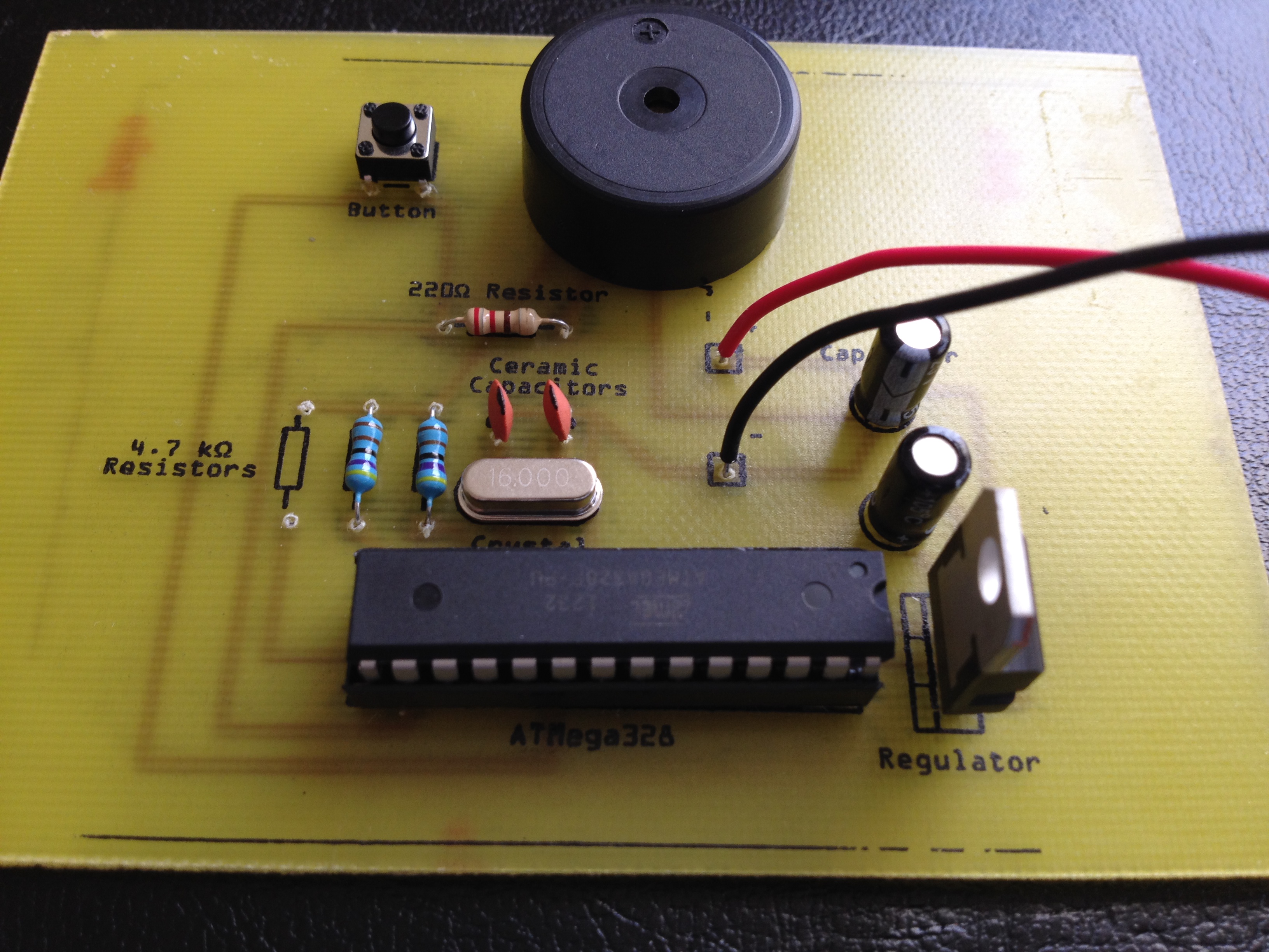
Here is the github page if you’d like to see the code and schematic: https://github.com/jerwil/Birthday_Card
Please DO NOT view the video demo, as it will ruin the surprise and satisfaction of hearing it work for the first time.
You can use miduino.net to convert any midi to arduino code. Just modify the pins to match the three pins attached to the speaker.
I hope that you are successful with this project! Hopefully this is a good intro to get you more excited about the blending of code and physical objects.