The Task & Background
One of my goals in the ATO Lab was to help other GE Oil & Gas labs automate testing and acquire data using LabVIEW-based designs. One of our sister labs is in Aberdeen, Scotland, and they do similar tests to those done in Houston. One of their electrical technicians wanted to learn LabVIEW, so I was sent out there for some hands-on learning.
I like teaching and tutoring, and I have found that one of the best ways to learn how to do something is to find a project that requires the target subject and work through it. So we brainstormed some ideas for automated systems that would benefit the lab, and we decided to make a system that would automatically perform pressure cycles on a valve.
Each valve that is tested in the lab must undergo a certain number of body pressure cycles. These cycles involve pressurizing the bore of the valve with nitrogen gas, holding pressure, checking for pressure drop, and releasing pressure. Most valves undergo 50 or more of these cycles, so it is very beneficial to automate this tedious process.
The Process
This project was primarily a learning exercise, so I sat down with the technician and helped him set up a cRIO and get some basic I/O working with a relay module and an LVDT position sensor. I then helped him install our preferred revision control system software (TortoiseSVN) and we did a checkout and a commit. From there, with the technician at the keyboard, we created the valve cycling system LabVIEW software from scratch using a simple state machine architecture.
The Hardware
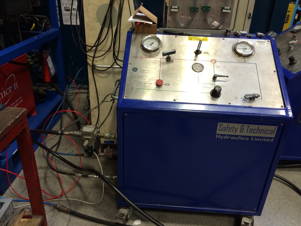
We modified an existing pump system and added high pressure air-actuated valves for pump control, pressure supply, and bleed. We also added a pressure transducer to read the pressure inside the valve, which is crucial for automated control.
For the electrical controls, we used a cRIO with an analog input module, a relay module, and a digital input module. The relay module allowed for the control of solenoid valves which would supply air to the air-actuated valves.
These normally-closed solenoid valves obtained their power through a circuit that passed through an E-stop button. If this button is pressed, all the solenoid valves relieve pressure, causing their corresponding air-actuated valves to close and for the pump to stop. A digital input line from the E-stop informed the software if the E-stop had been pressed.
The Software
Over a two week period, we created a state machine in LabVIEW that would perform the various steps in the cycle and check for pressure drop, timeout, and a variety of other errors. After showing the technician the basic architecture, I had him figure out the various state transitions and error checks needed to make the system work.
Testing
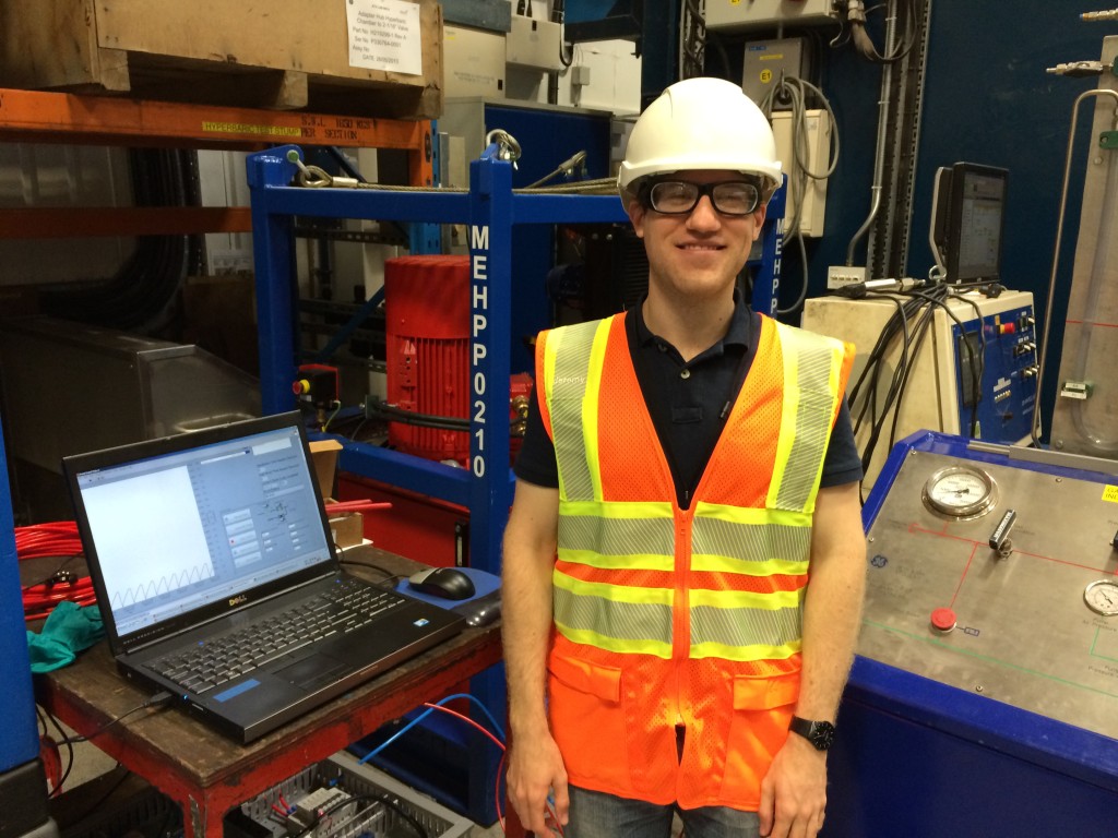
We got the system up and running and tested it on one of the valves on the shop floor. You can see me next to the interface in the photo below. The screen shows a strip chart of the valve pressure as well as the valve cycling controls.
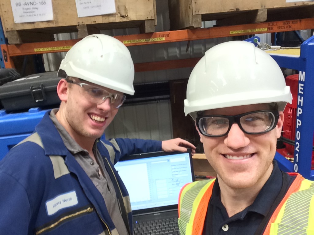
Overall the project was a success! The system ran well, and the technician learned some LabVIEW and how to set up and troubleshoot a cRIO Real Time system. Below is a photo of a proud technician and his creation: