Music Festival Beacon using ATtiny85 and Arduino

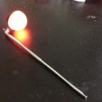
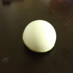
A couple months ago at Ultra Music Festival, one of my friends was carrying an inflatable penguin that he held above his head so that we can always find the group in the crowds of the festival. This gave me the idea to make a compact yet noticeable beacon. Using an old TV antenna and a ping pong ball, I created a light-up color changing beacon. This is what it looks like:

Here it is in action:

This showcases how the button is used to change the flashing speed as well as cycle through individual colors:

Here it is in use at a music festival! More more info, check out my field testing post:

Crowd-photo-1

The code, circuit diagram, and PCB layout are available here:

https://github.com/jerwil/ping_pong_light

How I Made It

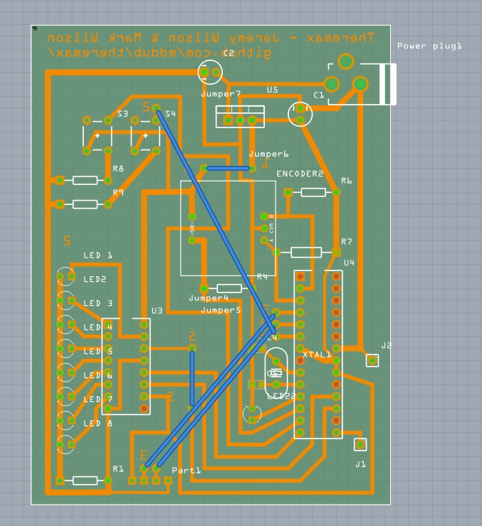
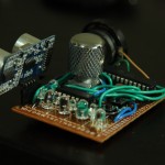
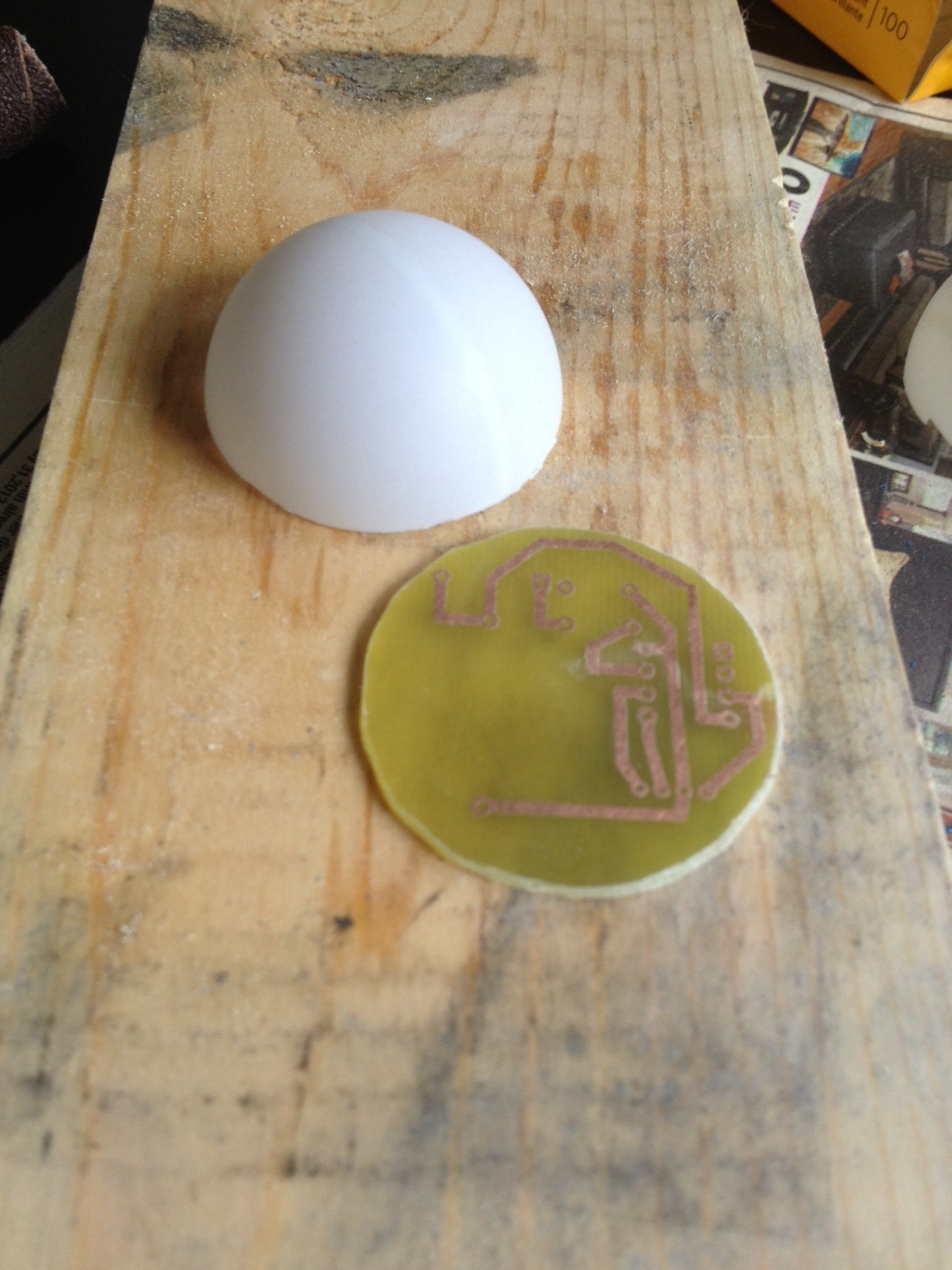
To start off, I programmed the ATtiny and got the circuit working on a breadboard, and then I designed the PCB using Fritzing. I knew that I was going to use a pong pong ball, so I matched the PCB to the ball’s diameter at 40mm.

beacon_breadboard

beacon_diagram

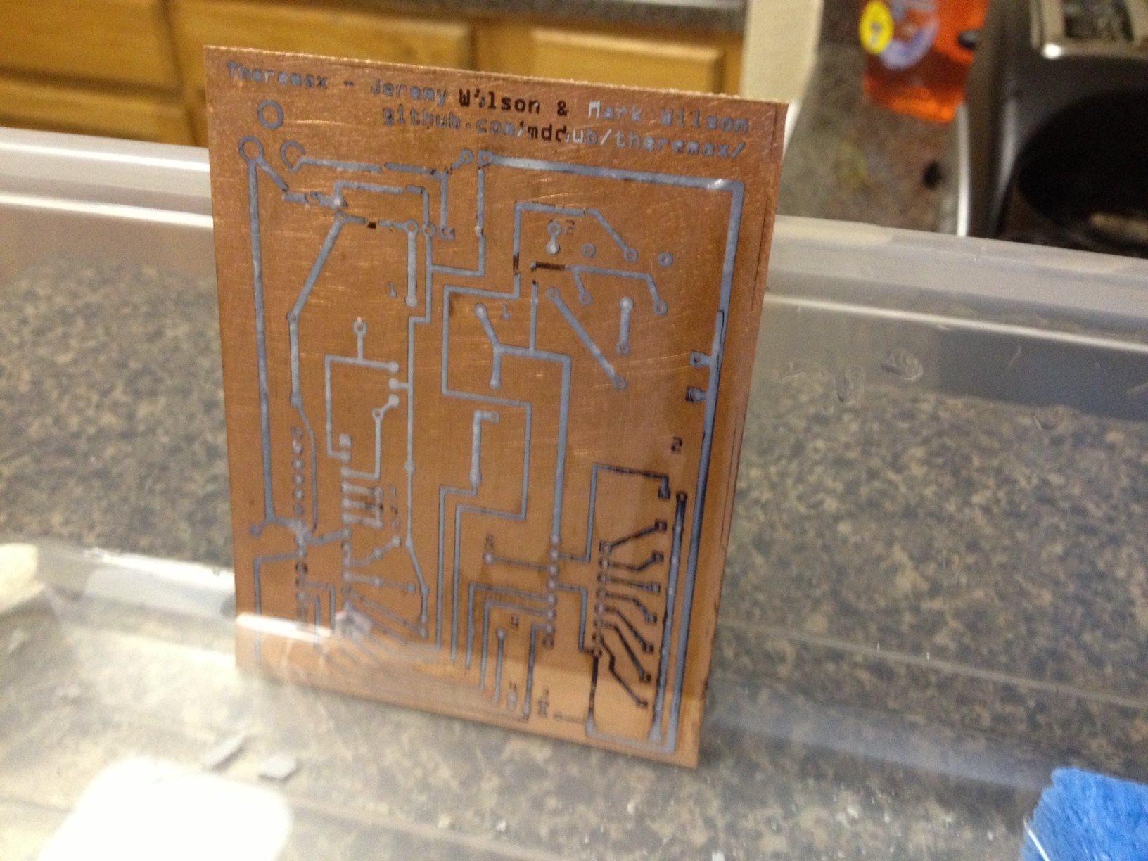
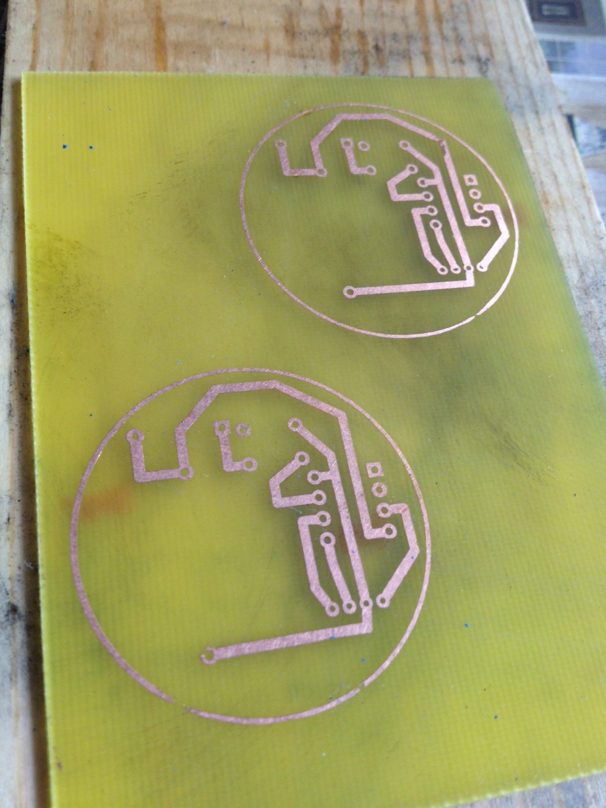
I then printed out the PCB diagram onto photo paper using a laser printer and transferred the image using a clothes iron.

image_2

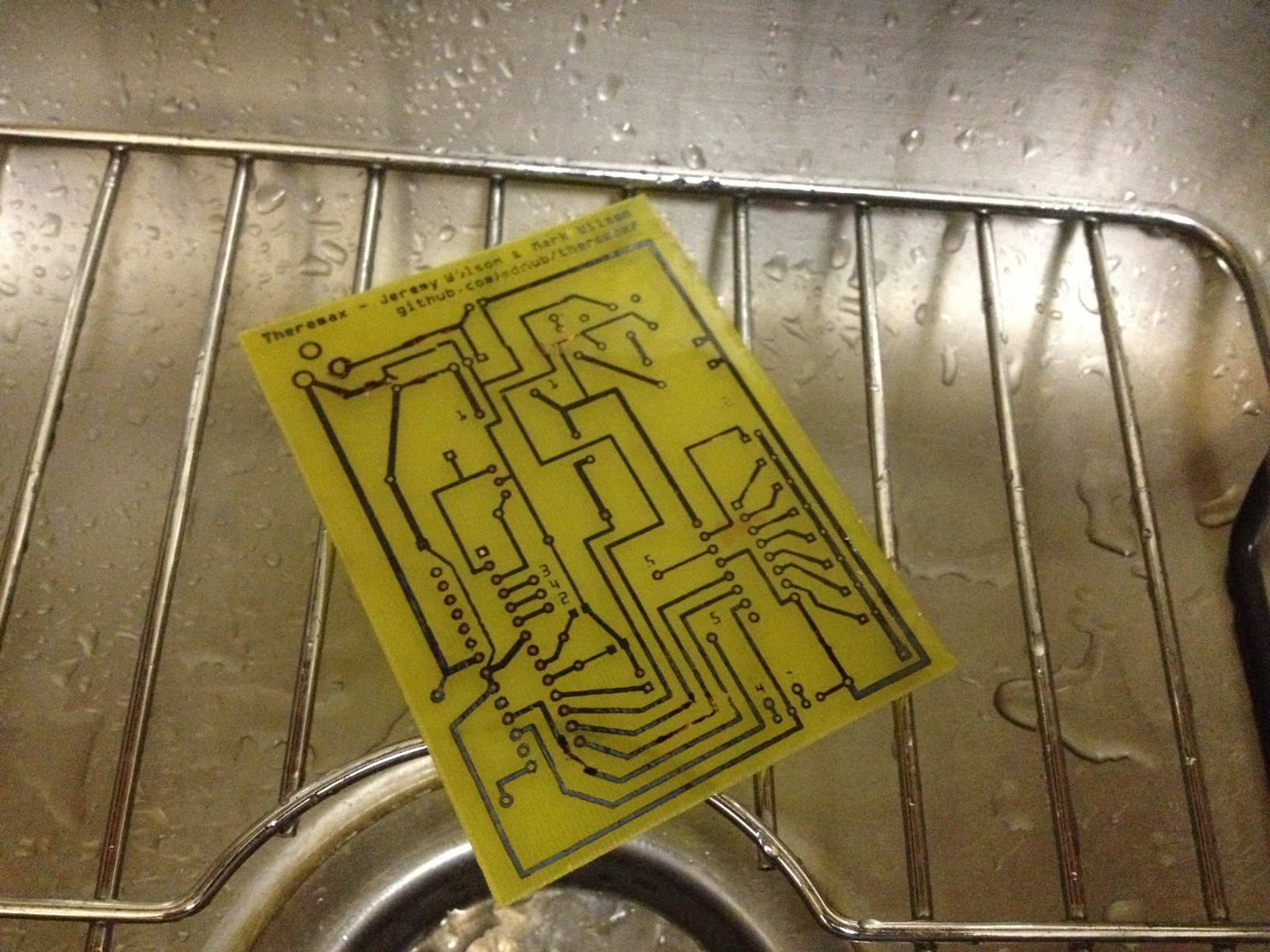
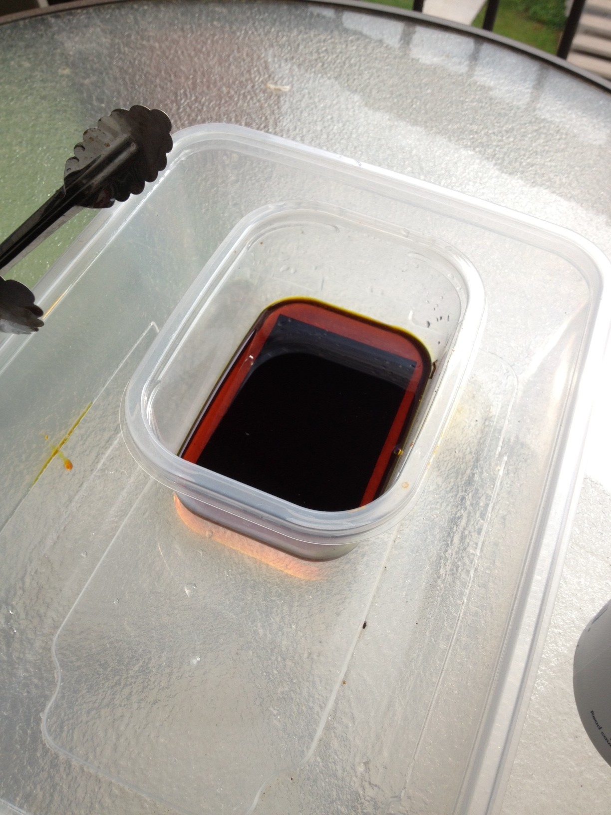
I then placed the board into a bath of Ferric Chloride for about an hour.

image_3

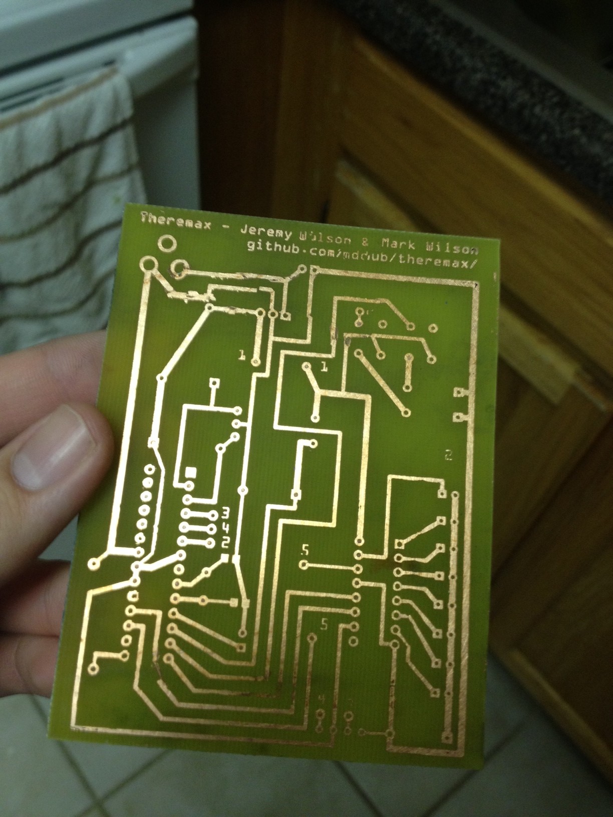
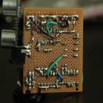
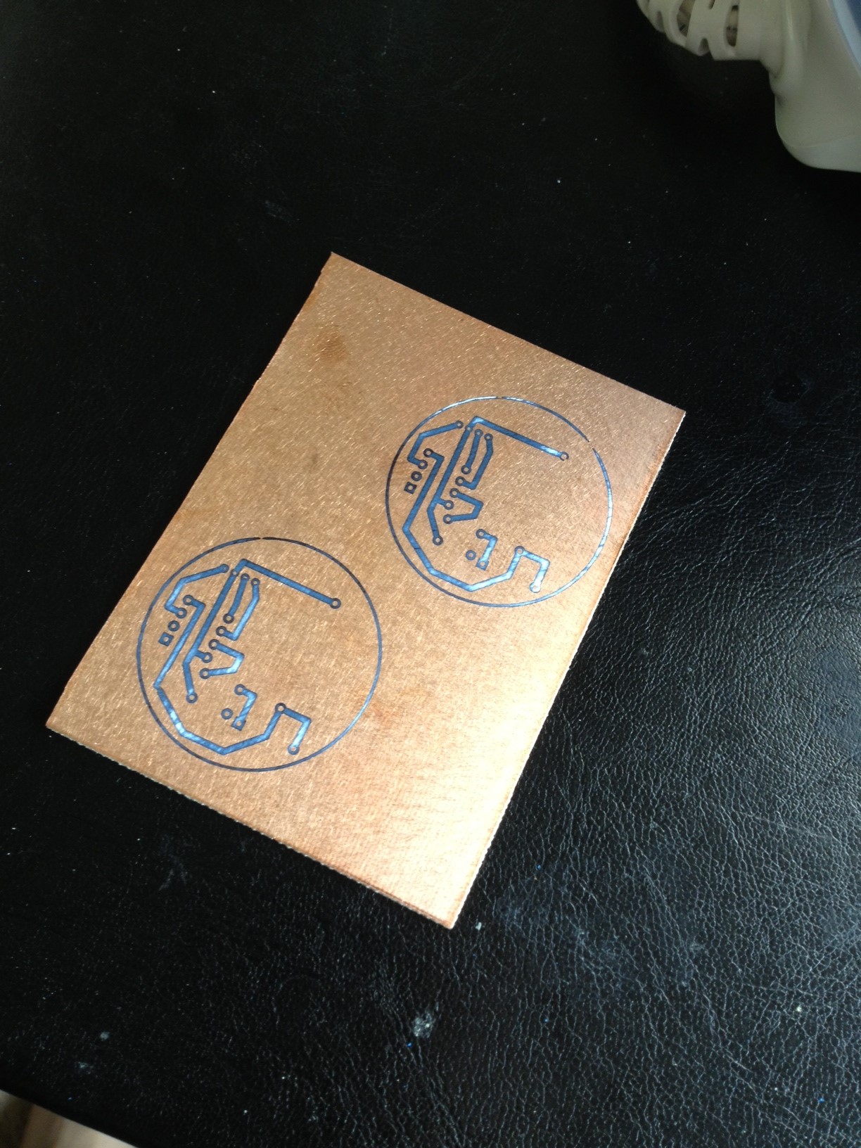
After cleaning off the toner, a pretty good etching job is revealed. I printed two on one board since I had the room in case of any problems with one of them.

image_5

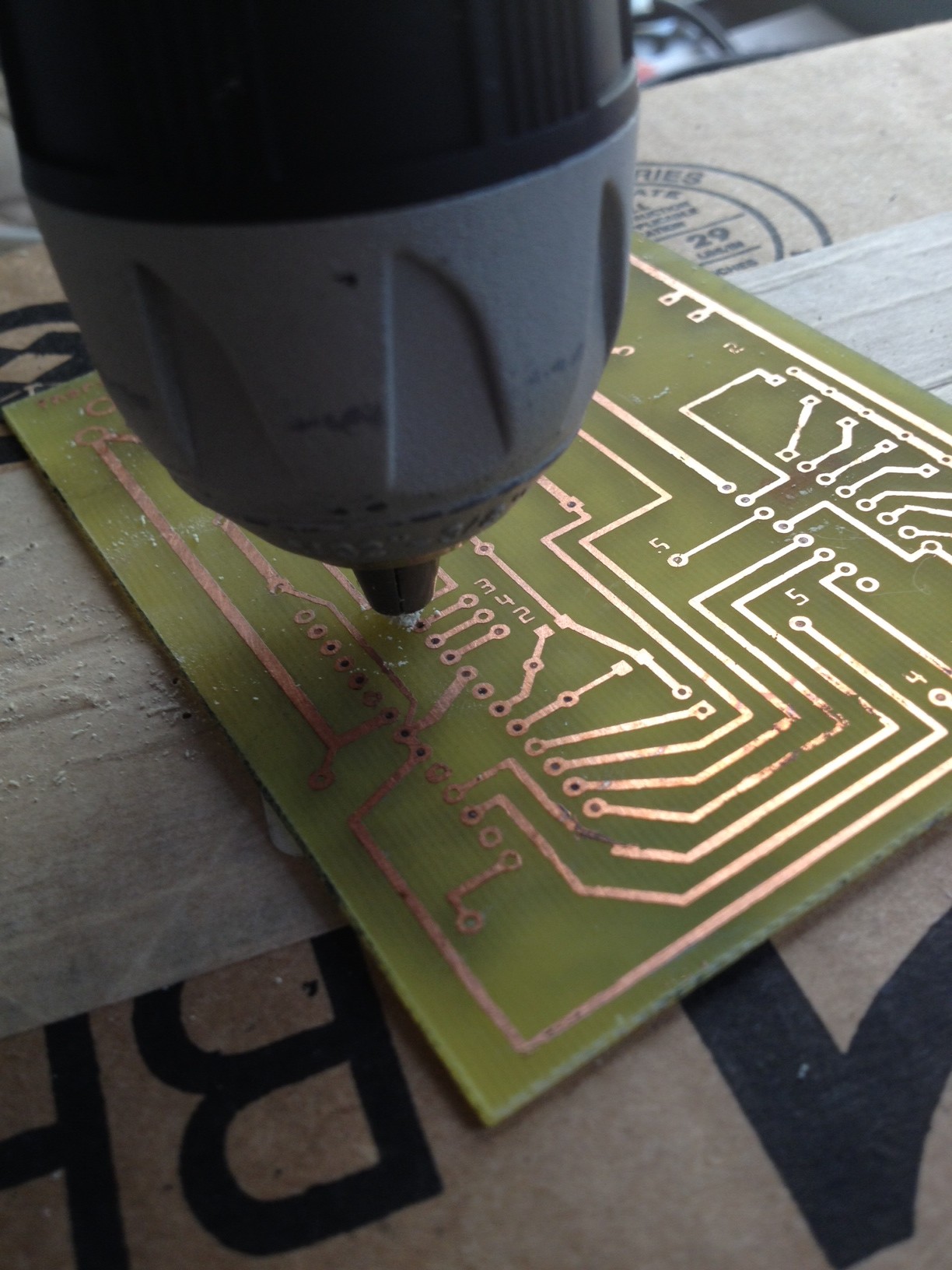
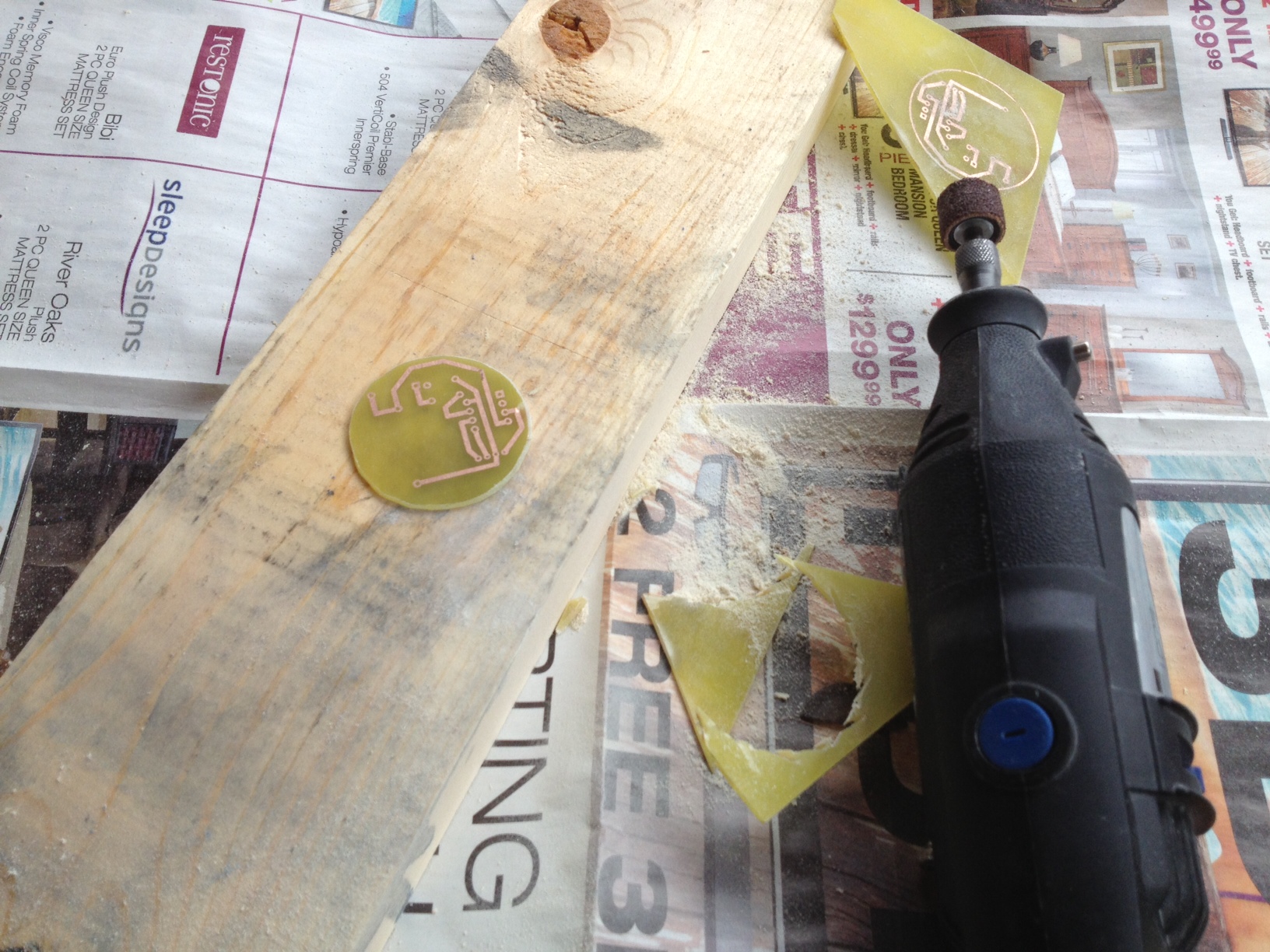
I am pretty inexperienced with the Dremel, so I was pleased to find it wasn’t too difficult to cut the outline of the board.

image_6

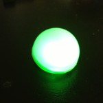
I then cut a ping pong ball in half with the Dremel. It fits the board nicely.

image_7

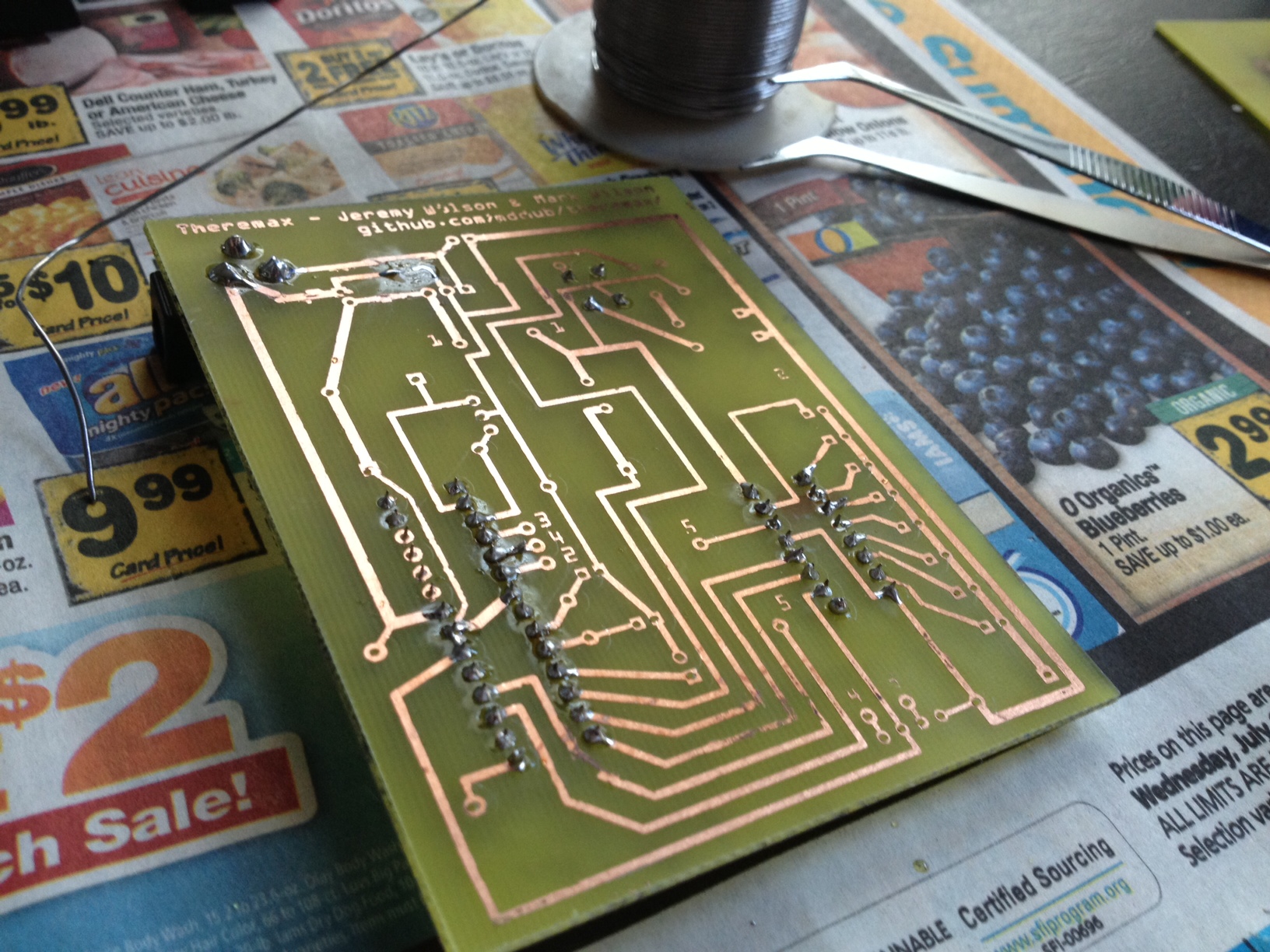
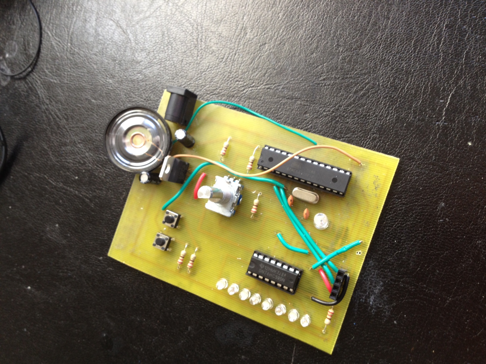
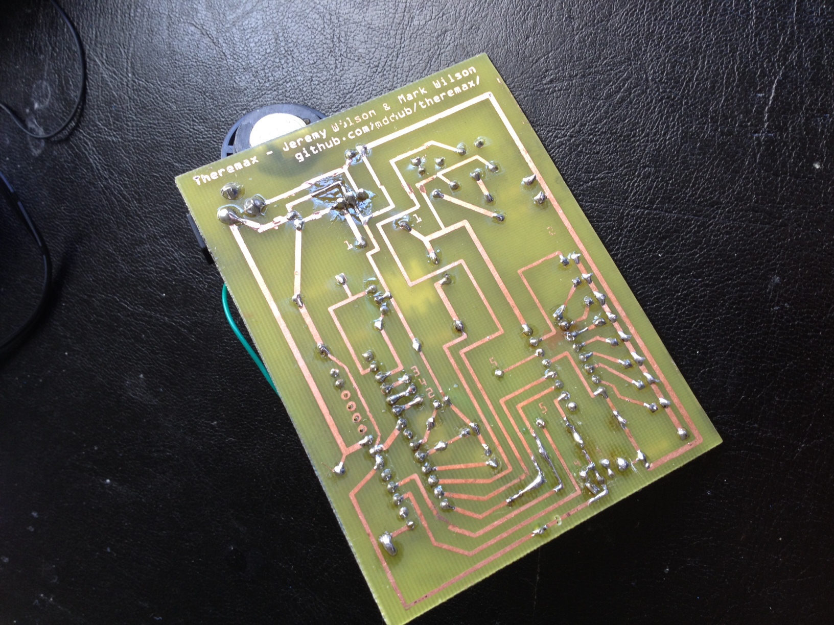
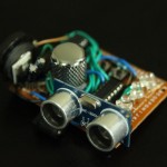
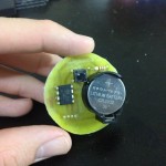
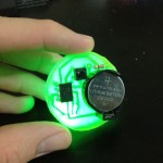
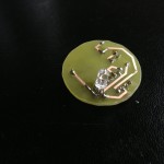
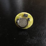
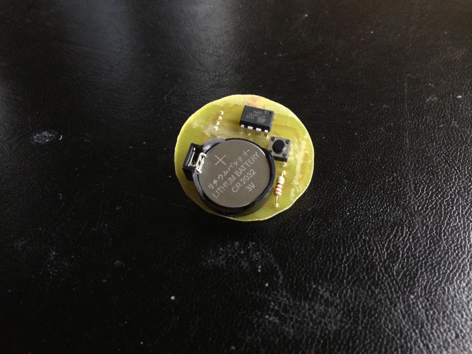
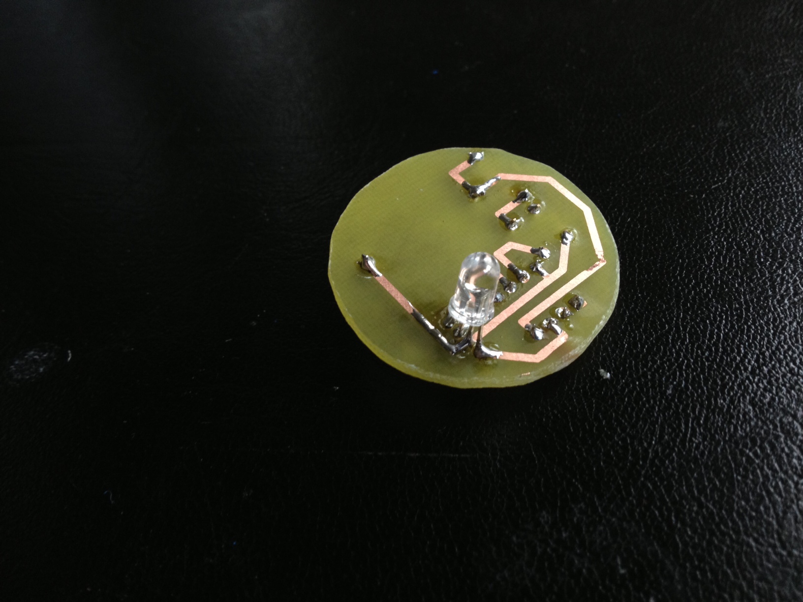
I then drilled the necessary holes and soldered on the parts. I wanted the button and battery to be accessible, but the LED to be on the opposite side. Here is the board:

image_9 image_10

This was a fun 12 hour project split over 2 days. One day for coding and design, and the second for etching and fabrication.

Theremax Pro Edition – Learning to Etch a Copper PCB

My brother and I spent a lot of time creating the Theremax, but we only produced one. We decided that I would keep the final product, and I decided that it would be a bit unfair. Thus, I decided to surprise him with his very own Theremax by trying out self-etching of my own PCB.

I started out by designing the PCB based on the wiring from the pre-perf PCB schematic I used to create the first Theremax. Since it is a single-sided PCB, I had to use some jumper wires to make it work.

Theremax_Fritzing_Diagram

I then printed the schematic onto photo paper and used a clothes iron to transfer the toner onto the copper board.

image

I then etched the board with ferric chloride for about an hour.

image_1

I then removed the toner with the rough side of a sponge. A successful etch!

image_2

I then used a 1/32″ drill bit to drill all the holes required.

image_3

I then began soldering on the components.

image_4

Theremax Pro complete!

image_5image_6

I am glad that I was able to learn how to etch and make my brother an excellent gift at the same time. Etching is not as bad as I expected, and I plan to etch all of my future projects to save hours of wiring and soldering onto pre-perforated boards.

Theremax – an Arduino theremin using an ultrasonic sensor

My brother and I spent a long weekend together in a hackathon-like fashion to create a theremin-like instrument using an ultrasonic sensor. The user waves his/her hand in front of the sensor to chose a note, and can adjust the octave using a knob. There is also a record mode which creates a loop that the user can edit on-the-fly.

Some photos of the final product:

The source code and circuit diagram can be found here:

https://github.com/mddub/theremax/

This project was made with the help of my brother, Mark Wilson. Check out his site: warkmilson.com

A video demo of theremax:

A time lapse video of the creation of the theremax:


Ikea Lantern LED Lamp – One Day Project

I’ve been working on a bunch of projects, but I haven’t been doing a good job of updating the site. To correct this, I am posting my simplest recent project. More projects to come in the next few weeks!

I recently hung up some lanterns from Ikea, and I noticed that the bottom of each lantern could have some room for some tinkering. Lighting up the candles is great for subtle illumination for watching movies at night, but I wanted a little more light out of the lantern. This inspired me to turn the lantern into a lamp using LEDs.

I used fairly simple materials for this project, mainly:

  • Foam board
  • White LEDs
  • 220 ohm resistors
  • Masking tape
  • White paper
  • 5 V regulator

I started out by cutting a piece of foam board to fit in the bottom of the lantern. I then cut a square out of the foam board:

image_2

I then started inserting LEDs into the foam board. I used a push pin to start each hole, and I then fed the LEDs through:

image_3

I soldered a 220 ohm resistor to the anode of each LED, and then hooked up all of the resistors to a power source in parallel. Here is me testing out all of the LEDs:

image_4

As you could see in the previous photo, I simply used masking tape as an insulator. It works, and it is fairly easy to work with. I then added the voltage regulator to enable the lamp to be powered by a 9V wall wart. I also glued on some pedestals on the corners for the paper to rest on:

image_5

I then wrapped the whole thing in a sheet of white paper to diffuse the LEDs. I super-glued a switch onto the lamp to turn the power on and off. This is what the lamp looks like in the daylight:

image_6

This is what the lamp looks like with the candle lit and the lamp turned on:

image_1

This is what both lamps look like:

image

I do not currently have any plans to turn the other lantern into an LED lamp since it is fairly close to my television and has nothing under it to illuminate, but if the asymmetry gets to me, I probably will end up upgrading it as well!

This was a fun, simple project to do. I have been using this lamp for a few weeks now, and  it works great as a night light. It is the perfect level of illumination for watching a movie, providing subtle yet useful light. A main goal of this project was to ensure that it is not obvious that the lantern is a lamp until it is turned on. With the light switch as small and subtle as it is, and the paper diffusion flush with the bottom of the lamp, I think I have accomplished this. This was also a test of LED diffusion for my largest project yet, coming soon…

Arduino Independence – Simon Game

I now have the Simon game working without an Arduino board! I wanted to be able to make several running projects without having to buy a board for each one, so I followed this guide: http://arduino.cc/en/Main/Standalone

In the photo above, the large circuit board is performing all the functions that the Arduino used to, including providing regulated power, a clock, a status LED, and connections for the I/O pins of the ATMega chip. The ATMega standalone chip with the Arduino bootloader preloaded can be purchased from sites such as sparkfun, or you can burn your own bootloader.

I can now program the chip in the Arduino then use it in an independent project. Now I just need to clear off these breadboards for my next project by soldiering it all on a PCB!

Simon on a Breadboard – Arduino Project

This project is still a work in progress. Functionally, it is complete, but I want to learn some soldiering skills by making it permanent on a PCB.

The idea for this project was to learn the basics of input and output with Arduino. This is my first real project, and I am happy with how it turned out. Before embarking on this project, I made sure not to google anything related to Arduino and Simon lest my mind become clouded with other’s ideas. I wanted to build this from the ground up, using my own inputs, outputs, and logic along the way.

The code and schematic can be found here:

https://github.com/jerwil/Simon_Breadboard

Arduino Photos

Here are some macro photos I took of some circuit related things: