Wedding RSVP Website

I had recently completed a web development bootcamp online, so I wanted to create a web application that was guaranteed to get some use in order to test my skills. With my wedding coming up, I decided to create a website for guests to RSVP online, saving postage costs and giving me a project to work on.

The back-end code was written in Node.js, with the front-end using bootstrap for quick and easy styling. The server-side code interacted with a MySQL database using the npm mysql package.

Invitees were given a randomly-generated 5-digit alphanumeric code to be used as a password for accessing their RSVP page.

If the information entered was valid, the invitee will be taken to a page showing their name and their plus-one’s name (if applicable). The database contained a field indicating whether a plus-one was allowed for each guest, and this form field would not be rendered if a plus-one was not given to the invitee.

As admin, I could login to see all the RSVPs, sorted by RSVP date. To keep things simple, boolean responses were reported as 1 or 0, which also made it easy to paste the table into excel for further processing.

Overall, the website was a success and received over 75 RSVPs successfully. It was a cool experience to create and manage a web application that saw real practical use.

Pikachu Light-up Costume

For Halloween of 2016, I wanted to create my own costume, something that would stand out. My wife and her friends all got animal onesies to wear for a night on the town, so I figured I’d join them, but with my own twist.

I bought a Pikachu onesie and picked up a couple of neopixel rings. I wired up the rings to an Arduino nano board and programmed a series of light patterns that the nano would loop through.

My wife then helped me sew the rings onto the costume, and Pika Cheeks was born!

I powered the setup using a USB battery pack that I kept in my pocket. The costume was a success, and lots of folks out on the street told me they liked it!

3D Printed iPhone Telescope Mount

I recently got a telescope, and I got a DSLR mount for it to take photos of astronomical objects. Ironically, after using both my DSLR camera and my phone’s camera to take pictures through the eyepiece, I found that I got better photos with the phone!

It was tough to keep it lined up with the eyepiece, especially while tracking objects in the sky, so I sought to create an adapter to hold my phone in place. I found a basic case design online and added to it. This is what I came up with in Onshape:

The case is intended to keep the phone’s camera centered on the eyepiece. Since eyepieces have a standard outer diameter, this should work for most of them. It’s also easy to slide the phone in/out of the case since I removed the bottom half from the design.

The design file can be found on the Onshape page here

I went to the local makerspace in the downtown library, and here is what the resulting 3D printed product looks like:

The printer I used did not use support material, so I split the design and glued the two pieces together, using the camera hole’s outline as an alignment guide.

The case design is pretty thin, so it ended up cracking on the left side. Thankfully, the phone still stays firmly in the case even with the crack.

Here are some photos I took with it:

Here is what the building looks like without the telescope (but with maximum digital zoom on my phone):

When the sky clears up, I’m looking forward to trying it with the night sky.

VR Block Buster – 72 Hour Game Development

Fairly recently I found out about Ludum Dare, the 48-76 hour game making challenge. Since I had just begun learning the basics of Unity, I decided I wanted to join the thousands of others who compete to get positive votes on their games.

For the December competition, the theme was “one room,” but during the theme voting phase, one of the potential themes was “you are the projectile.” This stuck with me, and I thought it would be cool to make a VR game where you are the projectile. So I made the game, and put it in a single room scene.

I’m pretty proud of what I was able to accomplish in a long weekend. Out of 2390 games submitted, mine ranked #340 for the “fun” category, which puts it in the top 80% of all games in the competition. I’ve also had friends play the game, and the feedback has been pretty positive. 

The premise is simple: you are in a room with lava on the floor and several blocks set up on a table. In VR, you use your head to aim a cannonball, and then press the button to launch your ball to knock as many blocks as possible into the lava. Here are some gameplay gifs:

A gameplay video can be seen here: https://www.youtube.com/watch?v=1eR9A1jOVuY

You can play the game on android with a VR headset or in the browser on PC here: http://ludumdare.com/compo/ludum-dare-37/?action=preview&uid=125143

The source code is available on my GitHub: https://github.com/jerwil/VRBlockBuster

Sonicare Head Holder

I am a big fan of the Sonicare toothbrush, but I’m not a fan of how large the heads are and how hard they are to store between uses. Since my girlfriend and I share a base, we always have a need to store the heads when we’re not brushing our teeth.

Since my bathroom is tiny, I wanted to be able to have something that would hang on the wall. I searched online, but I couldn’t find any existing products that would work. Thus, I decided to design my own hanging Sonicare head holder. This is what I came up with:

IMG_20150910_202701768_HDR

It is a laser-cut design made of white acrylic. The heads slide on, and the vents allow for any trapped moisture to escape. I used nodes on the interlocking portions to make the pieces better fit together.

IMG_2693

If you’d like to make this yourself, check out the design files on the GitHub page. You can also buy it ready-made it on my Ponoko page.

Valve Pressure Cycling System

The Task & Background

One of my goals in the ATO Lab was to help other GE Oil & Gas labs automate testing and acquire data using LabVIEW-based designs. One of our sister labs is in Aberdeen, Scotland, and they do similar tests to those done in Houston. One of their electrical technicians wanted to learn LabVIEW, so I was sent out there for some hands-on learning.

I like teaching and tutoring, and I have found that one of the best ways to learn how to do something is to find a project that requires the target subject and work through it. So we brainstormed some ideas for automated systems that would benefit the lab, and we decided to make a system that would automatically perform pressure cycles on a valve.

Each valve that is tested in the lab must undergo a certain number of body pressure cycles. These cycles involve pressurizing the bore of the valve with nitrogen gas, holding pressure, checking for pressure drop, and releasing pressure. Most valves undergo 50 or more of these cycles, so it is very beneficial to automate this tedious process.

The Process

This project was primarily a learning exercise, so I sat down with the technician and helped him set up a cRIO and get some basic I/O working with a relay module and an LVDT position sensor. I then helped him install our preferred revision control system software (TortoiseSVN) and we did a checkout and a commit. From there, with the technician at the keyboard, we created the valve cycling system LabVIEW software from scratch using a simple state machine architecture.

The Hardware

IMG_0661

We modified an existing pump system and added high pressure air-actuated valves for pump control, pressure supply, and bleed. We also added a pressure transducer to read the pressure inside the valve, which is crucial for automated control.

For the electrical controls, we used a cRIO with an analog input module, a relay module, and a digital input module. The relay module allowed for the control of solenoid valves which would supply air to the air-actuated valves.

These normally-closed solenoid valves obtained their power through a circuit that passed through an E-stop button. If this button is pressed, all the solenoid valves relieve pressure, causing their corresponding air-actuated valves to close and for the pump to stop. A digital input line from the E-stop informed the software if the E-stop had been pressed.

The Software

Over a two week period, we created a state machine in LabVIEW that would perform the various steps in the cycle and check for pressure drop, timeout, and a variety of other errors. After showing the technician the basic architecture, I had him figure out the various state transitions and error checks needed to make the system work.

Testing

We got the system up and running and tested it on one of the valves on the shop floor. You can see me next to the interface in the photo below. The screen shows a strip chart of the valve pressure as well as the valve cycling controls.

IMG_0658

Overall the project was a success! The system ran well, and the technician learned some LabVIEW and how to set up and troubleshoot a cRIO Real Time system. Below is a photo of a proud technician and his creation:

IMG_0660

Work Training

 Arduino Training Sessions

While at the ATO lab, I wanted to share some of the knowledge I had acquired through my hobby projects. Many coworkers were interested in some of the projects I had been working on at home, and they wanted to know how they could do something similar. So I decided (with permission) to take a couple hours out of the week for hands-on Arduino training sessions.

IMG_20160412_161754

Starting at the most basic level of installing the software and running the blink sketch, I walked the class through topics such as:

  • Digital inputs and outputs
  • Reading from analog sensors
  • Scaling analog readings
  • Serial communication
  • Using PWM to control LED brightness
  • Installing external libraries
  • Reading from digital sensors
  • Outputting to a screen using the I2C protocol
  • If statements, for loops, while loops, functions

After two weeks of training, I had my students come up with a project using some of the parts I had. Here is what they came up with :

A bluetooth-controlled light

A bluetooth-controlled light

A stepper motor clock

A stepper motor clock

A badge access system

A badge access system

Automated plant watering

Automated plant watering

A parking sensor for the garage

A garage parking sensor


LabVIEW Real Time Training Rig

When you purchase a full license of the LabVIEW development system, you get access to self-paced online training. This is pretty great and allows for some good hands-on learning through coding exercises… that is until you reach the Real Time section which requires a specific set of hardware to actually perform the tasks.

IMG_0109

Thus, I made PR2D2, named after a standard temperature/pressure test we do in the lab (PR2) and everyone’s favorite droid. This board contains all the hardware needed to complete LabVIEW Real Time 1 and 2, enabling several developers in the lab to learn hands-on on their own schedule without the need to travel to a training center.

IMG_0006

I also made a label for it using our circuit board mill, with a Star Wars font and rebel alliance symbol for good measure.

Formal Training and Certifications

I have a LabVIEW Certified Developer status and have completed the following LabVIEW training modules:

  • LabVIEW Core 1
  • LabVIEW Core 2
  • LabVIEW Core 3
  • LabVIEW Real Time 1
  • LabVIEW Real Time 2

I am trained and certified to operate jib and gantry cranes up to 50 ton.

I have been trained and certified in Swagelok fittings and tube bending.

I have the radiation training certification necessary to operate an XRF tool.

I have had formal training and practice in GD&T.

Brinell Hardness Greenbelt Project

The Problem

Brinell hardness measurement is a rough measure of the material properties of a sample. It involves using a hard ball to indent the material being tested, and then measuring the size of the indentation. The larger the indentation, the softer the material is since the ball was able to penetrate deeper. Sounds pretty simple, right?

This process actually has many variables that can affect the end result.

The indentation can be performed using several different tools including a stationary air-driven press or a hand-pumped device that is clamped onto the item being tested.

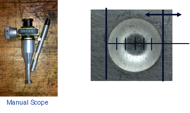
When reading the indentation, many different methods can be used. The cheapest method uses a handheld microscope-like device with two vertical lines. The user lines up one of these lines with the edge of the indentation and then twists a knob to bring the other line to the opposite side. By reading the amount incremented by the knob, the diameter of the punch can be measured. From there, the associated hardness reading is looked up from a table. Obviously this method includes a lot of human factors such as vision, motion accuracy, and correctly interpreting the result.

Manual scope diagram

In contrast, there are automated systems available which will capture an image of the indentation and calculate the hardness reading with minimal human influence.

Before indenting a surface, it must be smoothed using a grinder. This can be either a sand or stone based grinding wheel, and the grinding force applied can vary between inspectors performing the operation. This can work-harden the surface, and this effect depends on the original hardness of the material.

Our task was to determine how some of these variables affect the final hardness reading and propose solutions where needed.

Hardness Reading

The main focus of the project was the reading of the hardness punch. Different manufacturing cells used different methods of measuring the indentation diameter, so we wanted to see what kinds of errors resulted from each method. We devised a double-blind gage R&R test that had the inspectors check pre-punched samples using three methods of measurement: the manual scope and two competing automated systems.

iPhone Dump 6.1.14 1727

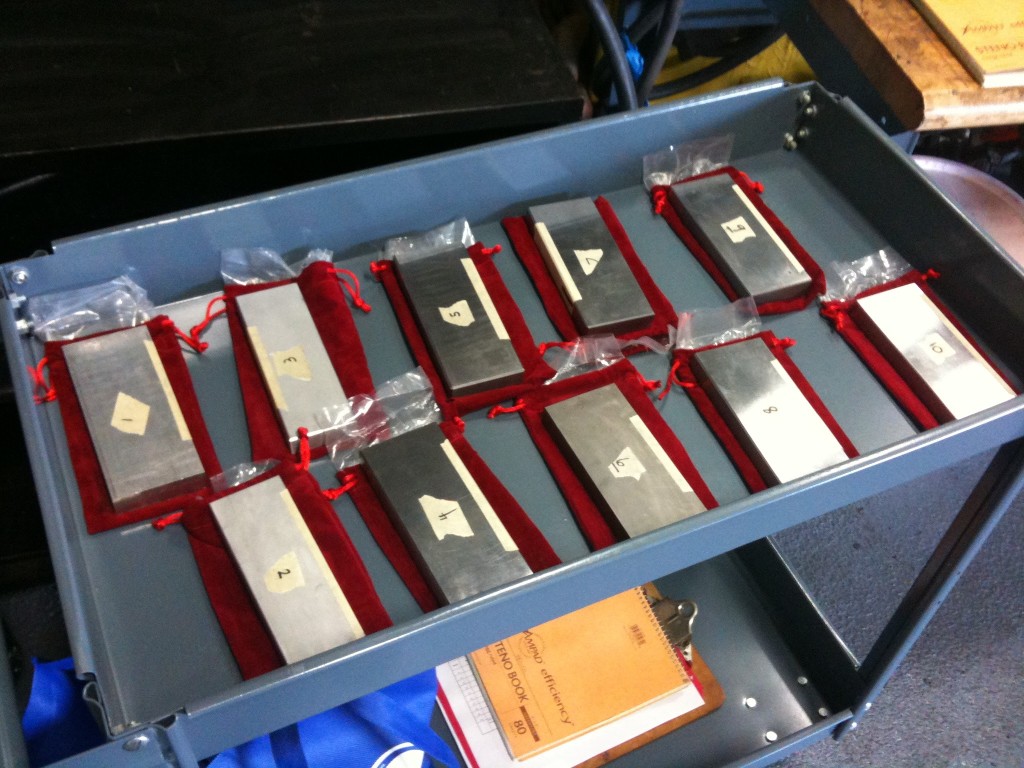
To obtain known hardness values, we used calibration blocks straight from the manufacturer. These blocks had 5 punches already made with hardness values disclosed for each. We covered up the hardness values, randomly assigned a number to each block, and then randomized the order in which the blocks would be handed to the inspectors. The inspectors would then test each punch and announce the result, which we would record. Each block was tested at least 3 times by each inspector with each punch measuring method.

Once all the data was gathered, we were able to remove the masking tape from each block, revealing its true hardness. We then compared the readings from the inspectors to the known values to compute the error in hardness reading using statistical analysis methods such as ANOVA.

Grinding

Another variable in the process is the way in which the surface is prepared. The two main kinds of grinding media are sand or stone, so these are the two that we tested. However, the user can exert any amount of force, which could potentially work harden the surface and skew the result.

Grinding hi res

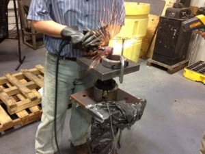
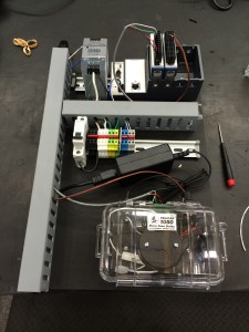
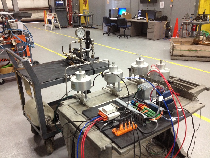
Thus, we devised a test fixture that would measure the load applied by the grinder using a load cell. I set up a simple data acquisition system using National Instruments hardware and LabVIEW, and we had the inspector grind softly, with moderate force, and with great force on various samples. We correlated the load applied to the resulting hardness reading to determine the effect (if any) of grinding force and media.

Heat Treating

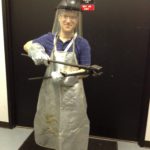
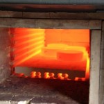
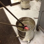
Another factor that applies to work hardening the surface is the initial strength of the material. To test this, we got to use an industrial furnace to heat treat samples to achieve material properties ranging from very soft to very hard.

These samples were used in the grinding experiment to see how much the hardness could be changed by the grinding process based on the initial hardness of the material.

Conclusion

While I cannot disclose the results of the study (it’s GE proprietary information), I can say that I learned a lot about material properties and hardness testing from this project. I was able to use many aspects of engineering to come up with experiments to test various aspects of the hardness testing process, and I got to interface with inspectors, cell leaders, shop floor managers, master black belts, material scientists, and even the vice president of engineering.

I was pleased to receive the following feedback from my manager:

“Thank you for the work you did on your Green Belt project. Your ability to work with various functions and groups enabled you to gather valuable data that led to critical changes to improve the hardness reading process. The experience and knowledge you gained during this process will benefit you as you grow in your career. Thank you for putting forth a tremendous effort!”

Diverter Seal Test System

This was my very first automated test that I was responsible for. I learned a lot of lessons along the way that have stuck with me for every project since.

The Goal

This test involved using a hydro-pump to pressurize two elastomeric seals. The customer wanted to pressurize the seals, hold pressure, bleed pressure, and then repeat until failure. Every 500 cycles, the seals needed to be leak tested by performing an extended hold and checking for pressure drop. If a seal failed, testing on it should cease, but the other seal should continue to be cycled until failure.

The Hardware

This was the first time I designed both the plumbing and electrical controls for a test.

Since each seal needed to be tested independently, each one had its own air-actuated isolation valve. On the pressure supply side, an air-driven hydro pump was turned on/off with a solenoid valve that supplied shop air. The supply side also had an accumulator which would be pumped up during hold periods, significantly reducing cycle time by increasing the speed at which the seals would fill with water. A common bleed valve was used to depressurize the seals between cycles.

Diverter Test Setup 1

The electrical board housed a cRIO with the necessary analog input and digital output cards. To control the air-actuated valves, a manifold with solenoid valves was used to convert electrical signals to valve actuation.

The Software

The interface had a simple plumbing schematic as well as manual and automatic controls. If a seal failure was detected, a large red indicator would light and the seal would be automatically isolated for the remainder of testing.

iPhone Dump 6.1.14 5149

Performance and Lessons Learned

The system worked well at first, detecting seal failure by checking for a percentage of pressure drop during the hold periods. However, a failure mode crept up on me that I didn’t account for: if the seal failed during pump-up, it would leak and never build enough pressure to move to the next test step. Thus, one day when we arrived to the lab, there was water all over the floor since the pump just kept on trying!

From that day forward, all automated system test steps included some sort of time-out to ensure the system stops the test if a condition is not met within a reasonable amount of time.

Family Day Projects

Bicycle Pump Race

Bike Race Photo

This was my first-ever LabVIEW automation project. Two players compete to inflate their bicycle tire to the target pressure in the shortest time. For each tire, I plumbed up a manifold with a pressure sensor, solenoid valve, and bicycle pump. Until the countdown starts, the solenoid valve bleeds pressure to avoid any cheating. Once the race starts, the valve closes and the players can inflate their tires. Once one of the tires reaches the goal pressure, a winner is announced and the solenoid valves open to bleed pressure and make ready for the next pair of challengers.

LabVIEW Pong

The classic game pong re-imagined with LabVIEW! Based off the LabVIEW Simple PONG 2 player game in the NI community pages. I modified the code to take in an integer as the pong paddle’s position, and then I wired up a couple of laser distance sensors to provide the player’s location. We flipped a projector 90° to face the floor, and I modified the interface to be white on black with square “pixels” for a retro experience.

Ultrasonic Instrument

IMG_6188 Crop

Taking inspiration from my Theremax project, this simple device takes in a distance reading from an industrial ultrasonic sensor and generates a tone from a speaker and lights up a ping pong ball using an RGB LED.

Mini Flow Loop

IMG_0228

I wired and set up the proportional valve, flow rate sensor, pressure sensor, and temperature sensor on this small-scale flowloop and wrote the software to control it. Its purpose is to show how flow rate and flow restriction influence pressure and temperature in flow.