Wedding RSVP Website

I had recently completed a web development bootcamp online, so I wanted to create a web application that was guaranteed to get some use in order to test my skills. With my wedding coming up, I decided to create a website for guests to RSVP online, saving postage costs and giving me a project to work on.

The back-end code was written in Node.js, with the front-end using bootstrap for quick and easy styling. The server-side code interacted with a MySQL database using the npm mysql package.

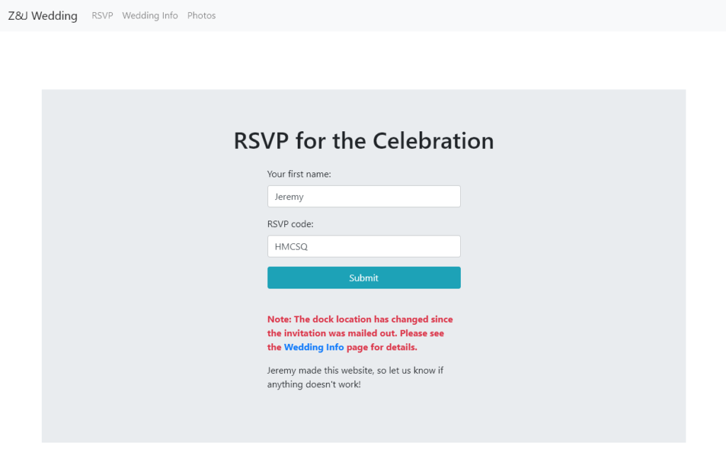
Invitees were given a randomly-generated 5-digit alphanumeric code to be used as a password for accessing their RSVP page.

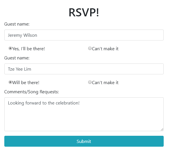
If the information entered was valid, the invitee will be taken to a page showing their name and their plus-one’s name (if applicable). The database contained a field indicating whether a plus-one was allowed for each guest, and this form field would not be rendered if a plus-one was not given to the invitee.

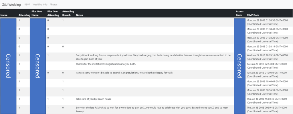
As admin, I could login to see all the RSVPs, sorted by RSVP date. To keep things simple, boolean responses were reported as 1 or 0, which also made it easy to paste the table into excel for further processing.

Overall, the website was a success and received over 75 RSVPs successfully. It was a cool experience to create and manage a web application that saw real practical use.

Pikachu Light-up Costume

For Halloween of 2016, I wanted to create my own costume, something that would stand out. My wife and her friends all got animal onesies to wear for a night on the town, so I figured I’d join them, but with my own twist.

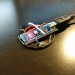
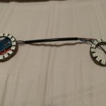
I bought a Pikachu onesie and picked up a couple of neopixel rings. I wired up the rings to an Arduino nano board and programmed a series of light patterns that the nano would loop through.

My wife then helped me sew the rings onto the costume, and Pika Cheeks was born!

I powered the setup using a USB battery pack that I kept in my pocket. The costume was a success, and lots of folks out on the street told me they liked it!

3D Printed iPhone Telescope Mount

I recently got a telescope, and I got a DSLR mount for it to take photos of astronomical objects. Ironically, after using both my DSLR camera and my phone’s camera to take pictures through the eyepiece, I found that I got better photos with the phone!

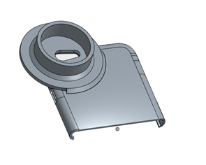
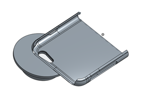
It was tough to keep it lined up with the eyepiece, especially while tracking objects in the sky, so I sought to create an adapter to hold my phone in place. I found a basic case design online and added to it. This is what I came up with in Onshape:

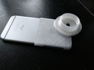
The case is intended to keep the phone’s camera centered on the eyepiece. Since eyepieces have a standard outer diameter, this should work for most of them. It’s also easy to slide the phone in/out of the case since I removed the bottom half from the design.

The design file can be found on the Onshape page here

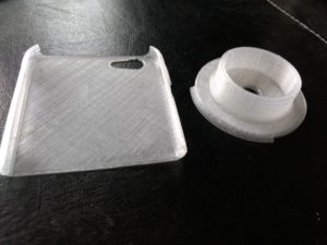
I went to the local makerspace in the downtown library, and here is what the resulting 3D printed product looks like:

The printer I used did not use support material, so I split the design and glued the two pieces together, using the camera hole’s outline as an alignment guide.

The case design is pretty thin, so it ended up cracking on the left side. Thankfully, the phone still stays firmly in the case even with the crack.

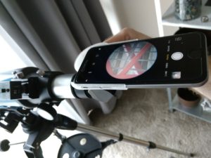
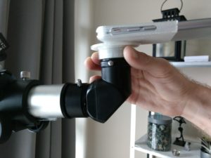
Here are some photos I took with it:

Here is what the building looks like without the telescope (but with maximum digital zoom on my phone):

When the sky clears up, I’m looking forward to trying it with the night sky.

VR Block Buster – 72 Hour Game Development

Fairly recently I found out about Ludum Dare, the 48-76 hour game making challenge. Since I had just begun learning the basics of Unity, I decided I wanted to join the thousands of others who compete to get positive votes on their games.

For the December competition, the theme was “one room,” but during the theme voting phase, one of the potential themes was “you are the projectile.” This stuck with me, and I thought it would be cool to make a VR game where you are the projectile. So I made the game, and put it in a single room scene.

I’m pretty proud of what I was able to accomplish in a long weekend. Out of 2390 games submitted, mine ranked #340 for the “fun” category, which puts it in the top 80% of all games in the competition. I’ve also had friends play the game, and the feedback has been pretty positive. 

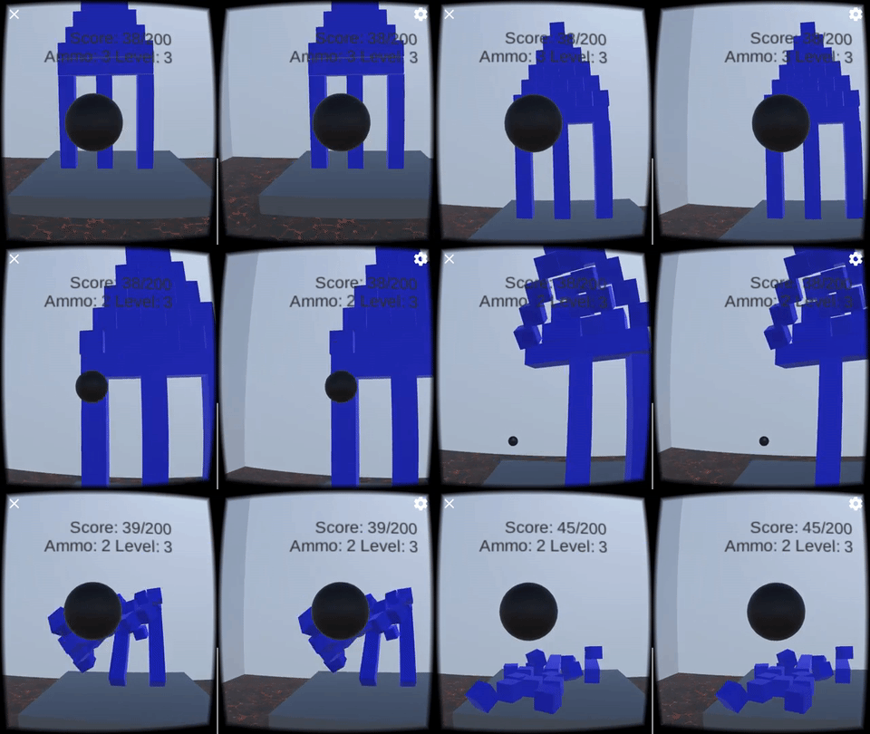
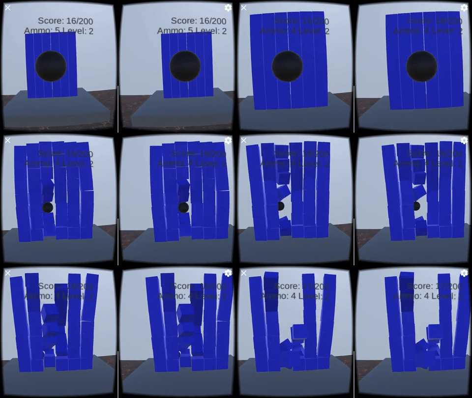
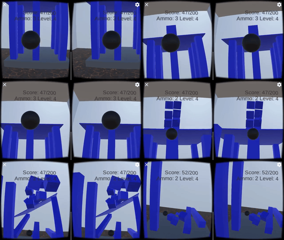
The premise is simple: you are in a room with lava on the floor and several blocks set up on a table. In VR, you use your head to aim a cannonball, and then press the button to launch your ball to knock as many blocks as possible into the lava. Here are some gameplay gifs:

A gameplay video can be seen here: https://www.youtube.com/watch?v=1eR9A1jOVuY

You can play the game on android with a VR headset or in the browser on PC here: http://ludumdare.com/compo/ludum-dare-37/?action=preview&uid=125143

The source code is available on my GitHub: https://github.com/jerwil/VRBlockBuster

Automating Time Lapse Workflow with Python

I love watching time lapses. I’ve even made some of my own in the past, for work and for fun. So, when I moved into a new apartment with construction going on right outside my window, I knew I had an opportunity to capture its progress using time lapse photography.

This is the guide I have been using to construct time lapses from a collection of photos.

The Goal

Unlike some of the time lapses I’ve done in the past, this one is expected to go on for at least a year (or more depending on how long I stay in this apartment). That means that the system I set up has to be robust and reliable so I don’t miss large chunks of time. However, I’m also very frugal, so I wanted to be able to do all this with a $20 android phone.

The Setup

Capture Software

In order to store thousands of photos reliably, I decided to FTP them to a server, rather than trying to store them all on the phone’s SD card. I found that the impressively featured MobileWebCam app for android could save straight to an FTP server.

Hardware Setup

Originally I set up my ZTE Maven on my windowsill. Unfortunately, the charging port is on the side of this budget phone, so it had to be “upside-down” as far as MobileWebCam is concerned. This meant for a little more post-processing in VirtualDubMod to flip the image.

A sample upside-down image of the construction


Once I was happy with the phone’s capabilities, I decided to spend a few more bucks and mount the phone properly. I got a goose-neck mount and attached it near my window. Now my phone could have a clearer view, and it isn’t upside-down!

Phone in goose-neck mount


Making it Reliable

I wanted this system to take photos ad infinitum without me having to worry about the phone crashing or the connection to the FTP server breaking. Initially I had a calendar event every week to manually check the FTP folder and see if any new files came in. After a time, this got to be quite annoying, although I did catch the phone freezing a few times during this period.

There had to be a better way, so I thought of a reason to dust off the old raspberry pi: a python script to automatically check on the time lapse every day. I wrote the script (you can find it on my GitHub), and set up my pi to run it daily as a cron job. Basically, the script sees how many files are in the FTP folder, compares this value to what it found last time, and then sends me an email with the status. Much better than having to do it myself! Here’s an example email I would get:

Timelapse is working! We got 150 more files since last time for a total of 8234


Creating the Video – Challenges

Every so often, I will compile the photos taken into a time lapse video. Per the guide referenced earlier, VirtualDubMod is an excellent free choice for creating such a time lapse. Though VirtualDubMod is pretty picky, and it requires all image filenames to be contiguously numbered (such as 1.jpg, 2.jpg, 3.jpg, etc rather than 1.jpg, 4.jpg, 5.jpg, 8.jpg).

Generally this problem is solved using a bit of software called Ant Renamer, which can enumerate files with ease. The tricky part is that once the files are transferred from the FTP folder, the “created date” becomes the time the file was transferred. So the only way to sort the files is by name. This soon becomes a problem when you have files named something like:

  • 1.jpg
  • 2.jpg
  • 4.jpg
  • 6.jpg
  • 11.jpg
  • 12.jpg
  • 13.jpg
  • 22.jpg

Because this sorts as:

  • 1.jpg
  • 11.jpg
  • 12.jpg
  • 13.jpg
  • 2.jpg
  • 22.jpg
  • 4.jpg
  • 6.jpg

Another Python Solution

To solve this problem, I wrote another Python script I called the “File Name Length Equalizer” to add zeros to the beginning of each file name such that they became the same length. Then they could be sorted with ease!

Before and after equalizing file names

Once the files were sortable, I used Ant Renamer to enumerate them, and then imported them into VirtualDubMod and processed them per the guide.

This project posed a lot more challenges than originally anticipated, but it was fun to be able to come up with automated solutions that allowed me to get the end result I was looking for.

The Sleep Sensei

The Sleep Sensei is a device I created to help people fall asleep faster using calming breathing training. It’s for people who have trouble falling asleep, due to insomnia or an active mind at bedtime.

I ended up posting the Sleep Sensei on Kickstarter and had a successful campaign.

You can read more about the Sleep Sensei here: www.getsleepsensei.com

This post is the story of the Sleep Sensei and how it came to be.

The first (very rough) prototype

This whole project started because I have trouble falling asleep at night. I was looking at potential solutions and came across a smartphone app that produced a pattern of light to follow with your breathing as you try to fall asleep. The main problem with this is that the phone screen is so dim that you can’t see it without having your eyes open! This seemed counter-productive to sleep, so I sought a better way.
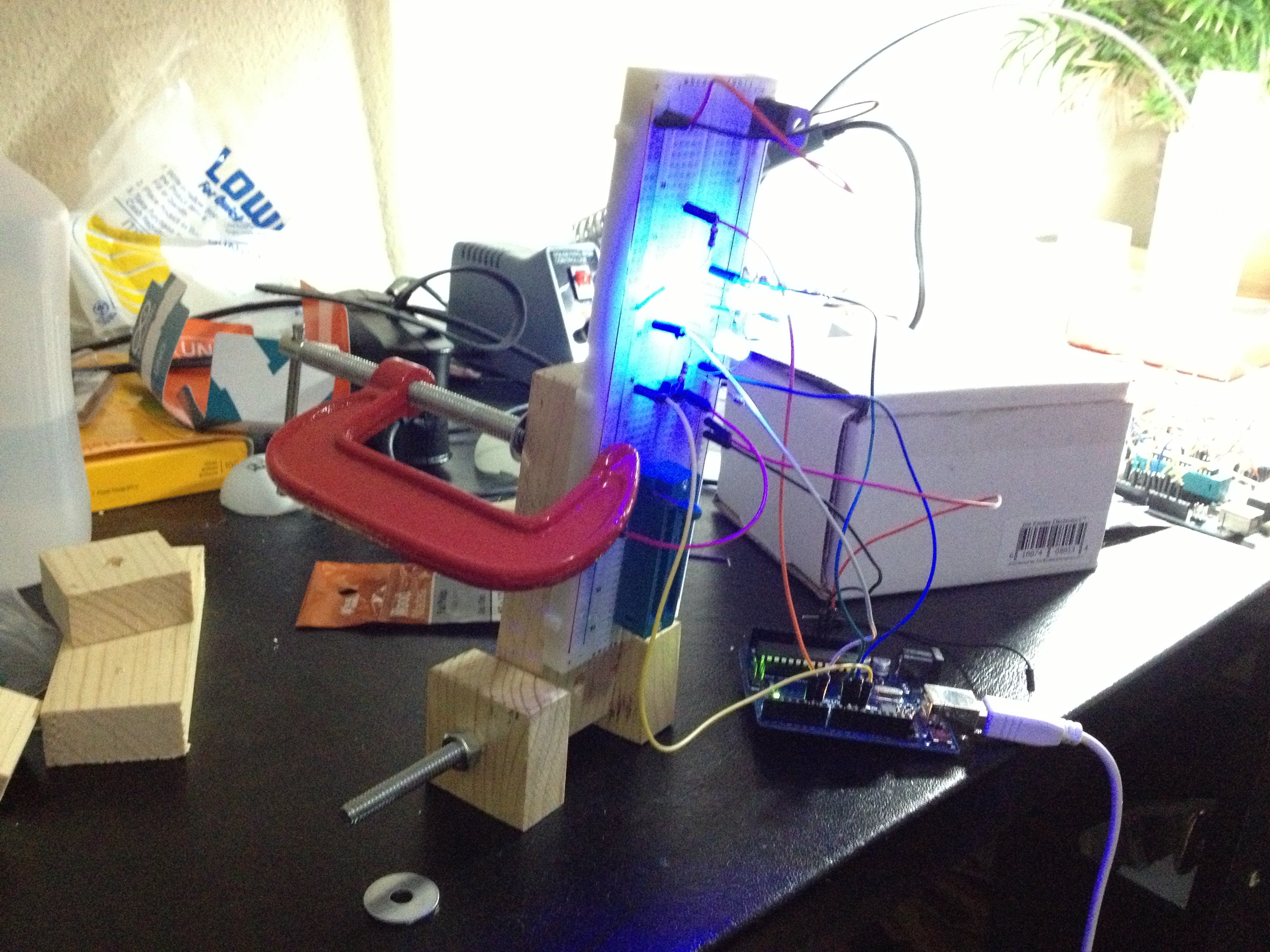
This is the very first prototype of the Sleep Sensei. It consisted of a breadboard with 4 blue LEDs performing a simple brightening and dimming cycle. I chose blue LEDs since the smartphone app I used performed a similar feat, and it used blue light. This was before I began researching the effects of various colors of light on sleep quality, so I didn’t really know any better.

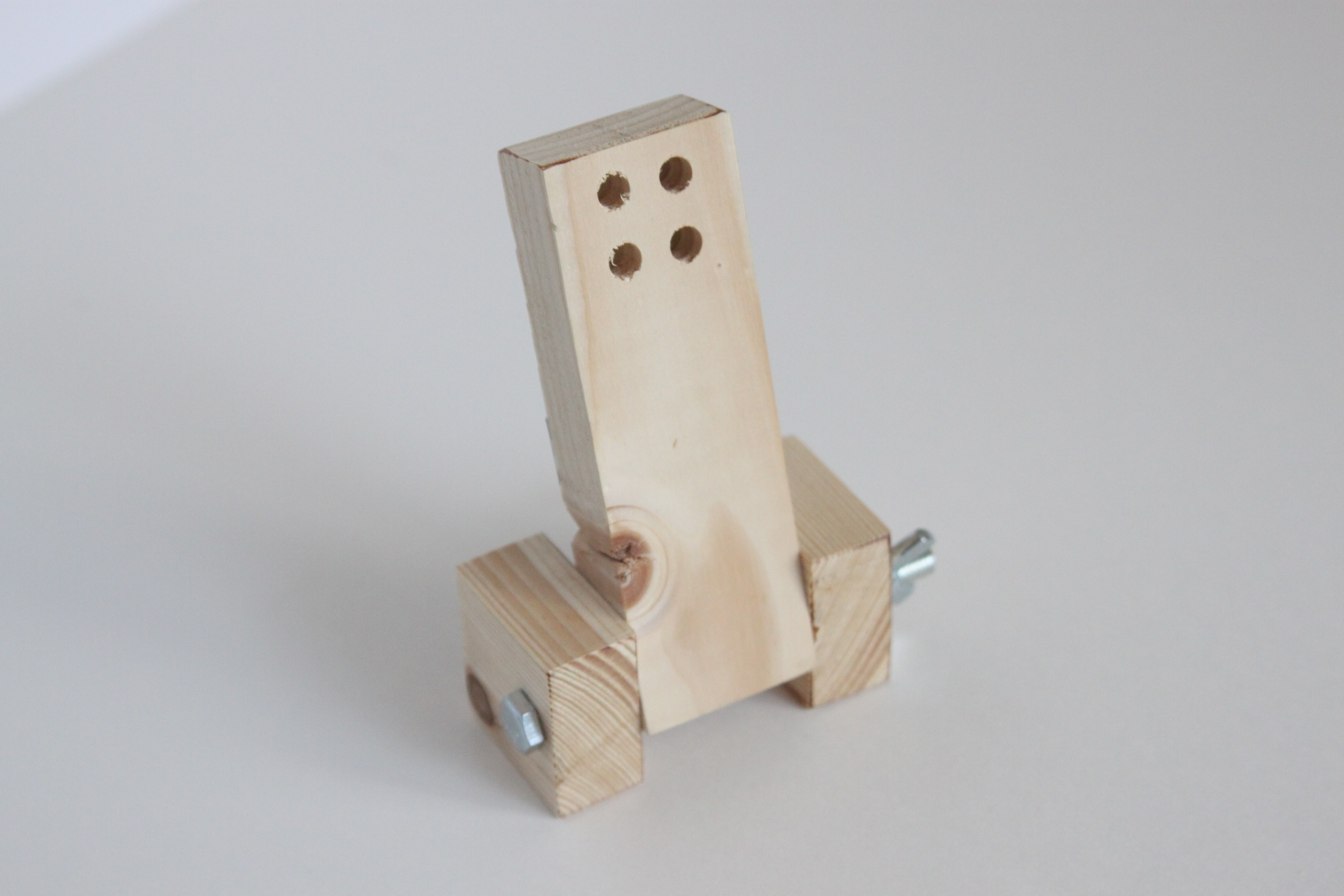
The breadboard was clamped onto a wooden base with a pivot to allow me to aim the light towards my eyes. The idea was that the light from 4 LEDs directed towards my eyes would be bright enough to be seen with my eyes closed through my eyelds. And it worked!

More prototyping, and the Kickstarter design

Standalone Prototype

I liked the idea of the Sleep Sensei enough to acid-etch a circuit board for what I breadboarded. I drilled 4 (very rough) holes into my wooden base so that the LEDs would shine through, and had my first standalone prototype!
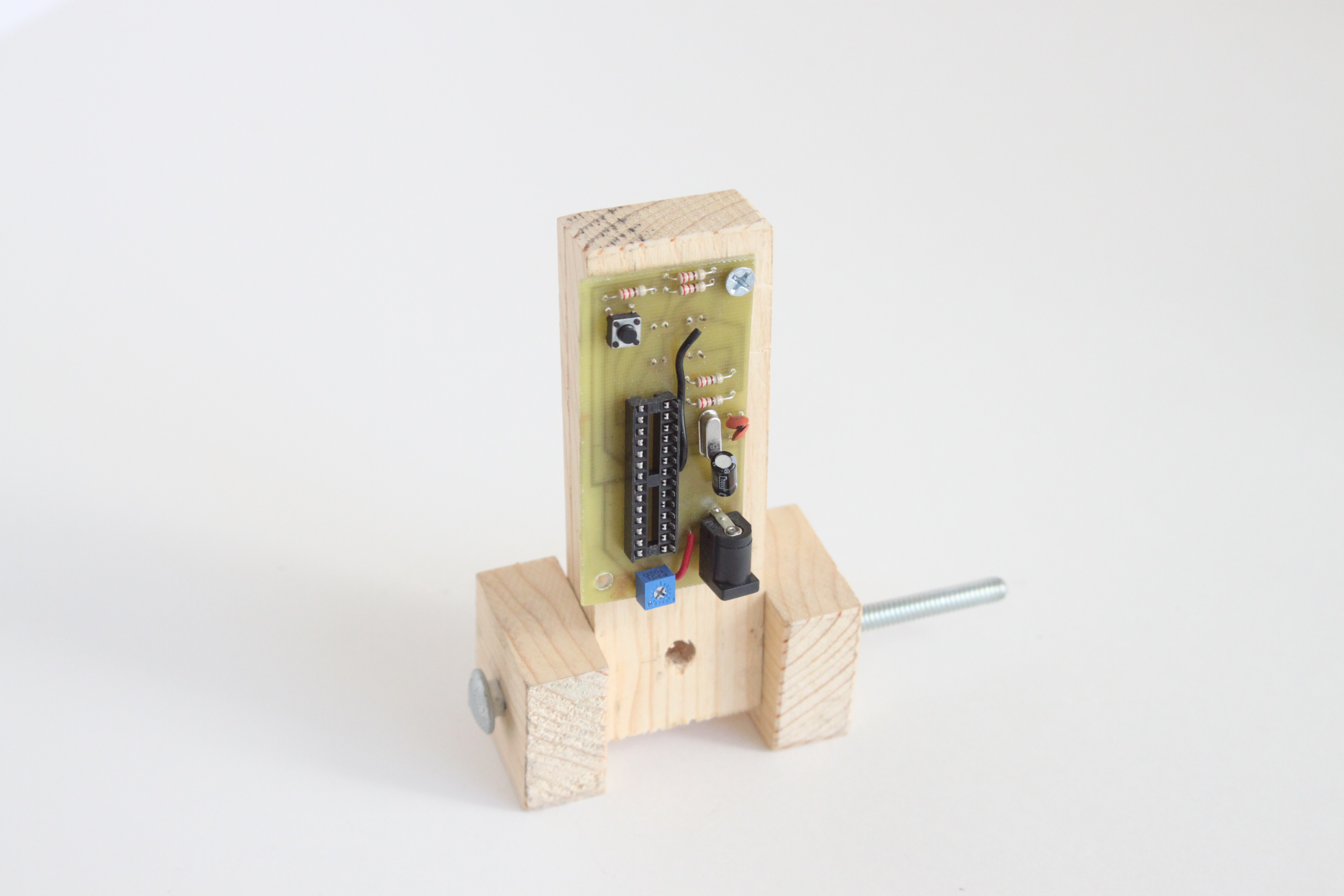
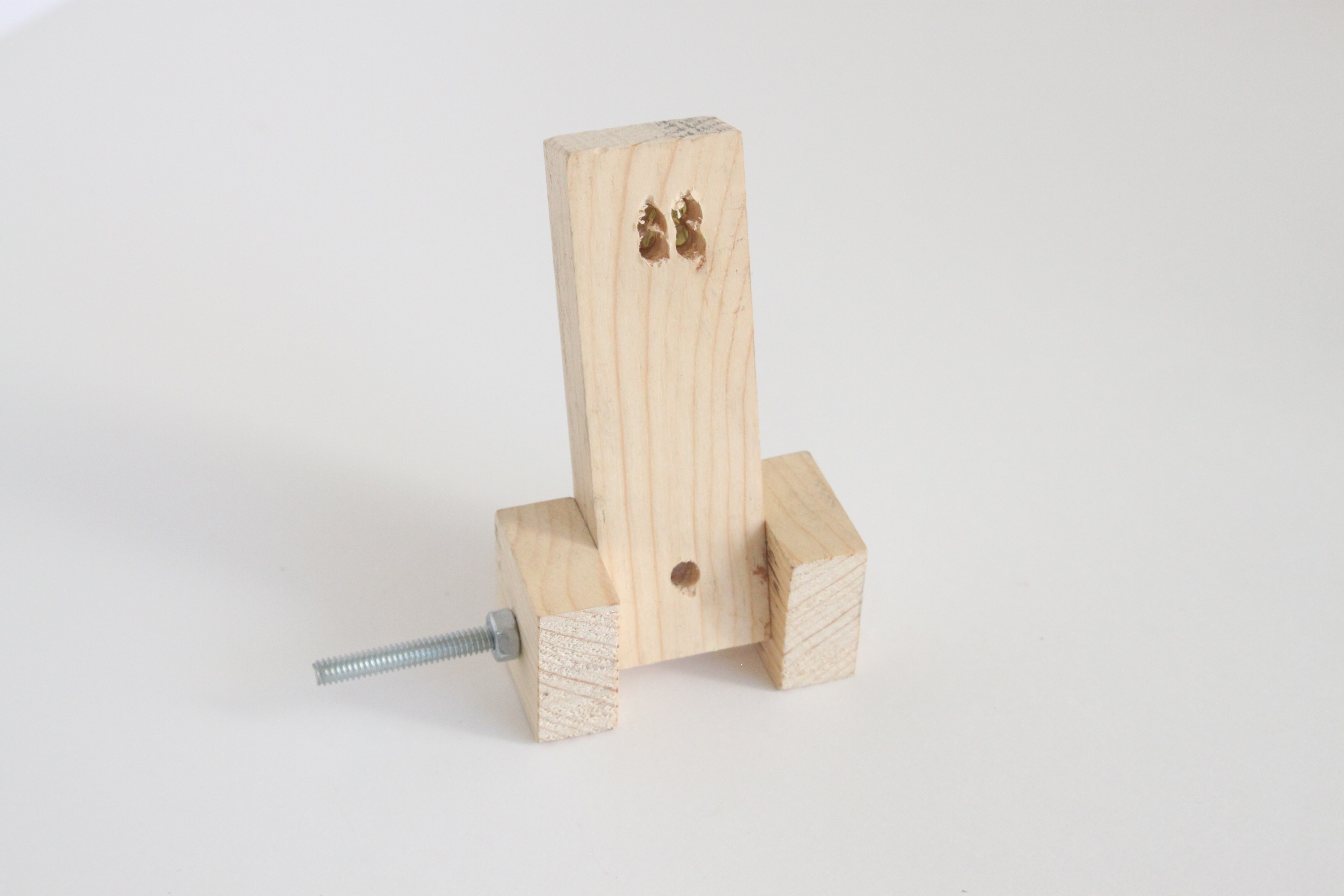
This prototype used an ATMega328, and it has a standard potentiometer to adjust the brightness. The button would allow you to switch between 4 durations of sleep coaching.

The First Decent-Looking Prototype

I ended up enjoying using my standalone prototype so much that I wanted to try to make more of these little guys to try on friends and family. I figured if it helped me fall asleep faster, it could help others as well. So I did some research and found out that I could program an ATtiny85 (much cheaper than the ATMega328) using Arduino, and whipped up a breadboard with all the necessary connections.
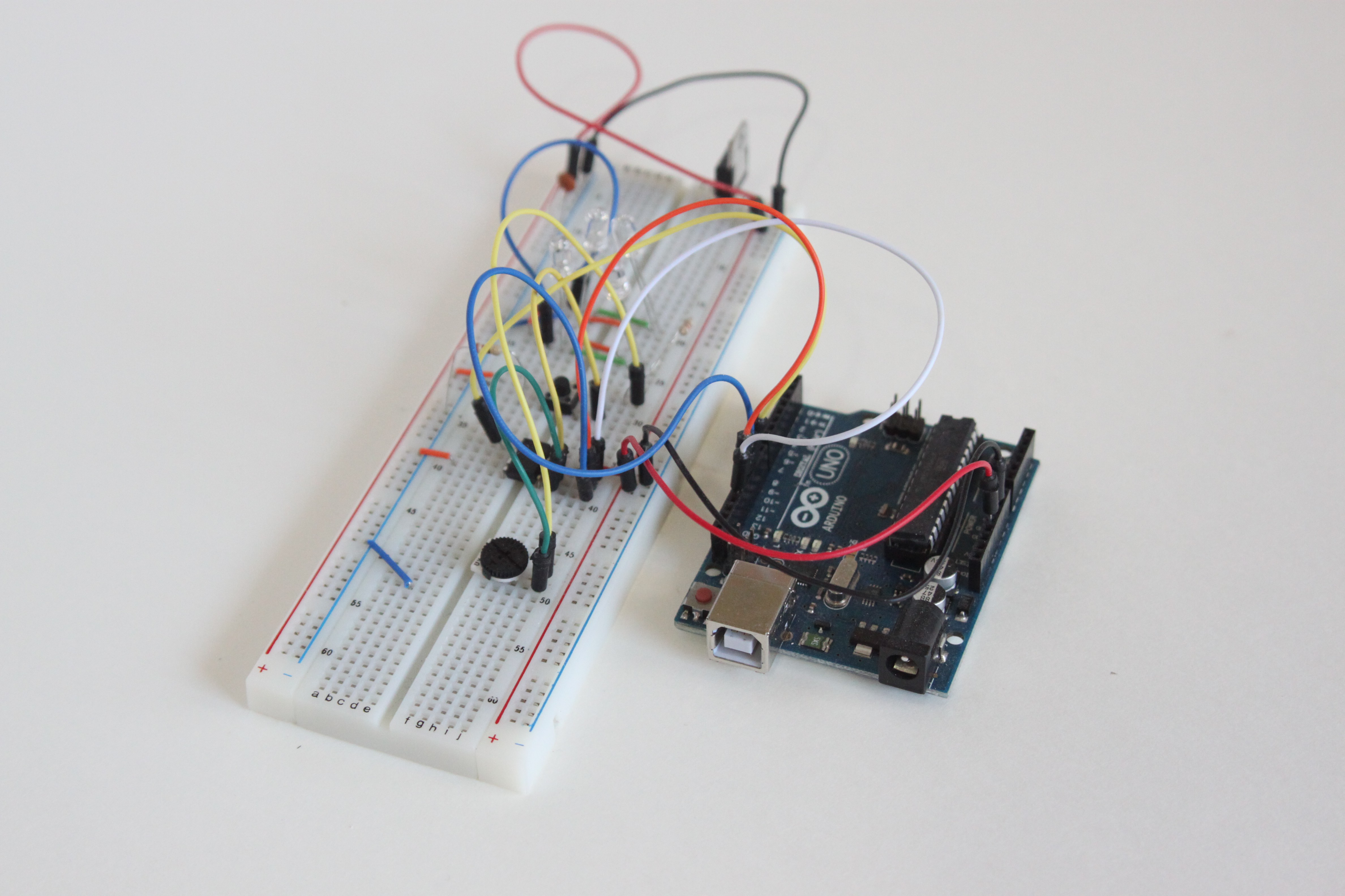
A challenge I had was timing, since the ATtiny85 was running at 8 MHz compared to the ATMega328’s 16 MHz. So I had to add a couple multiplication factors in the code to have the breathing pattern match what I had tuned on the ATMega-based design.

I then designed and acid-etched a new circuit board designed for the ATtiny85. I also found some nice thumb-wheel potentiometers on eBay which would allow for adjustment of the brightness without a tiny screwdriver. Here is what the prototype looked like:
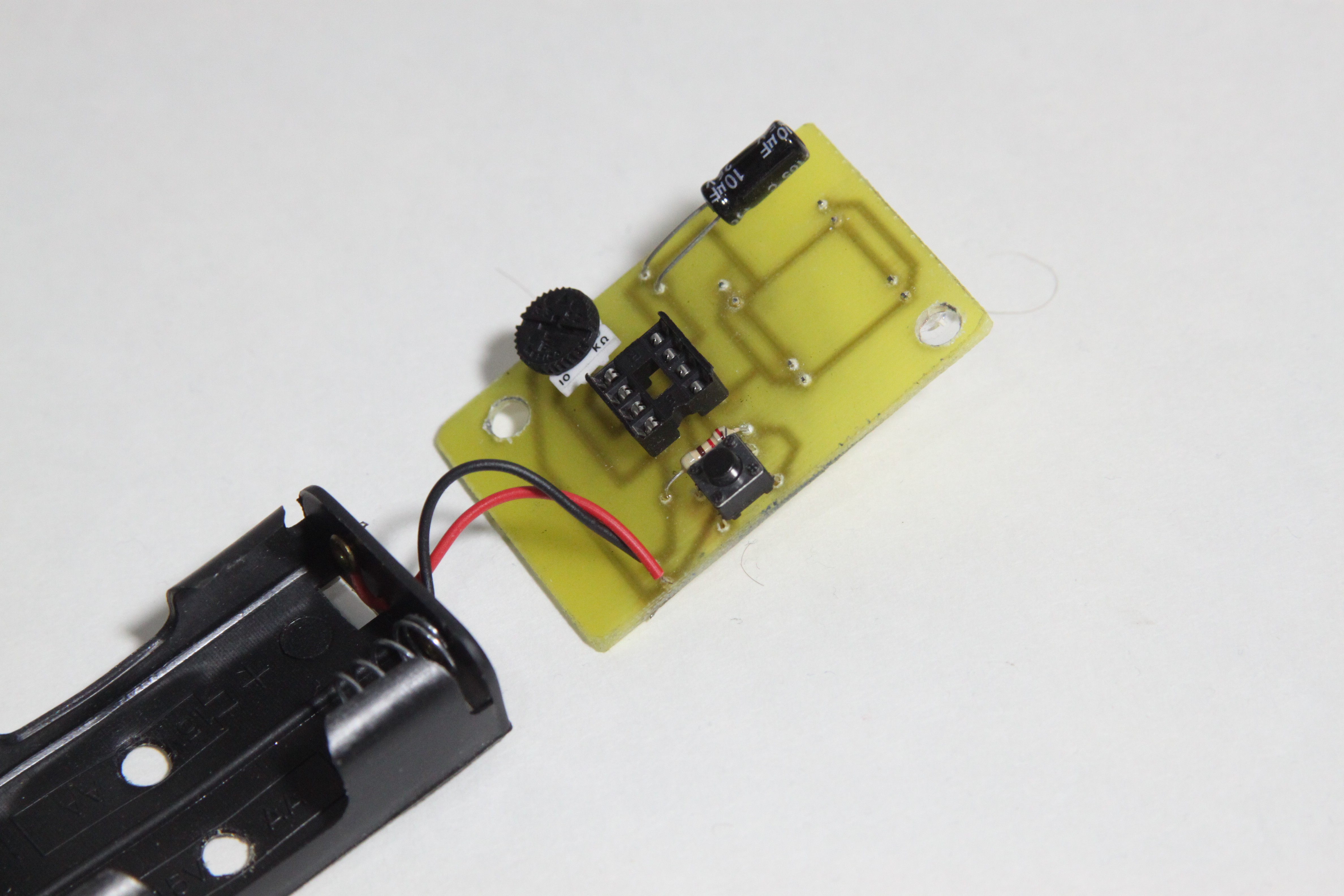
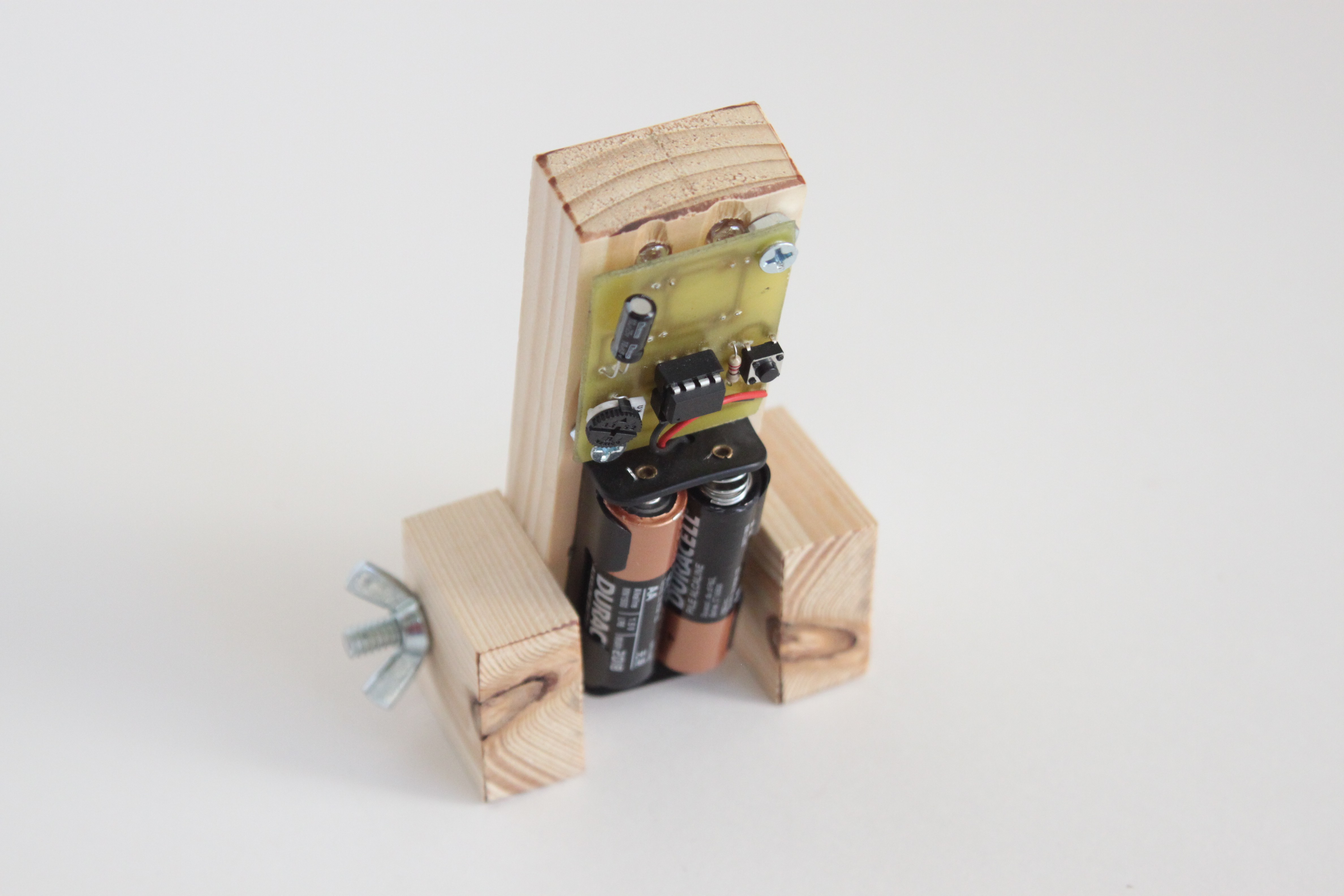
I used this guy for a few weeks, and it was actually pleasant to use. This time I had red LEDs (since I had done some research), and a nice compact circuit board that wouldn’t be too expensive to have professionally made. So that’s what I did:
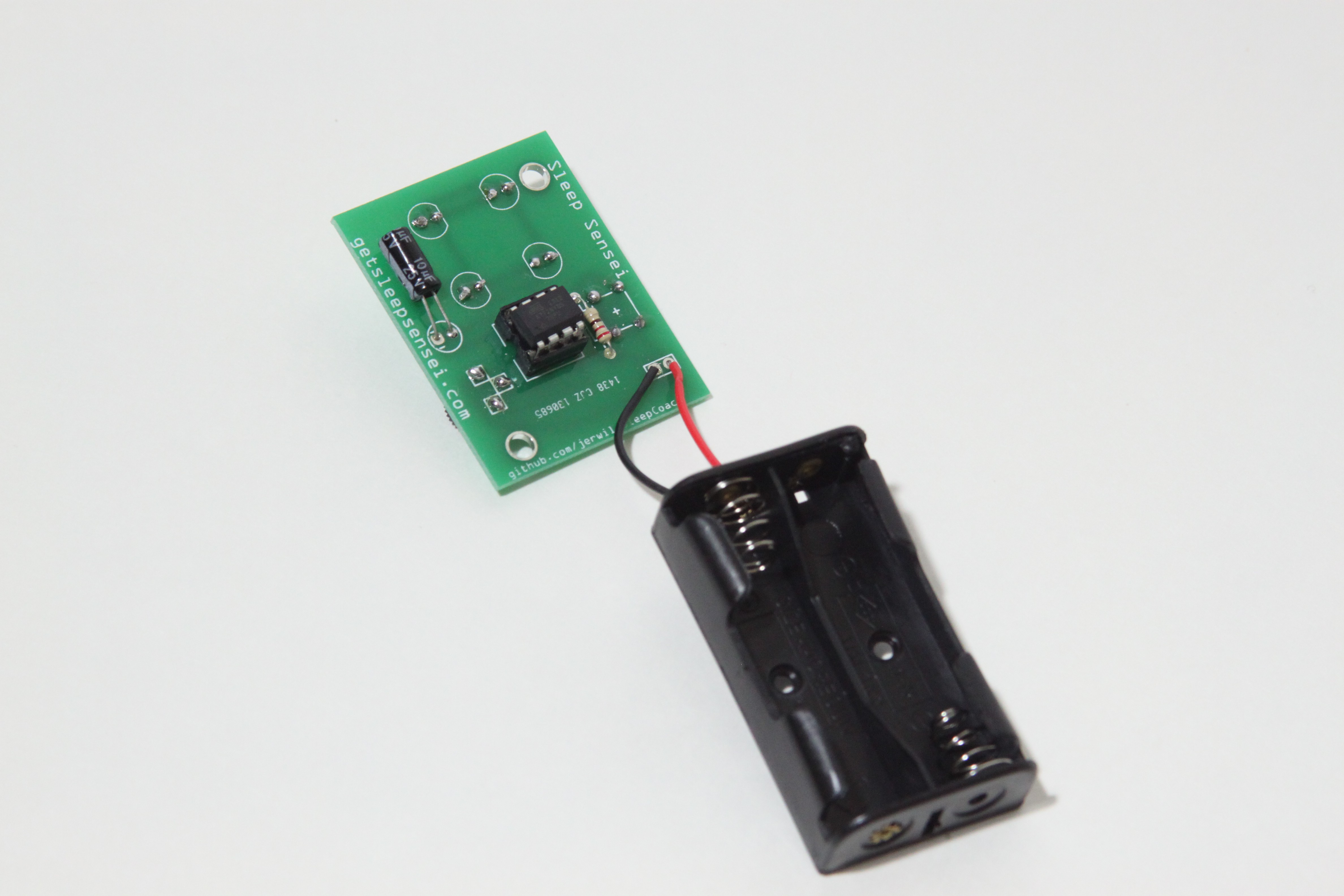
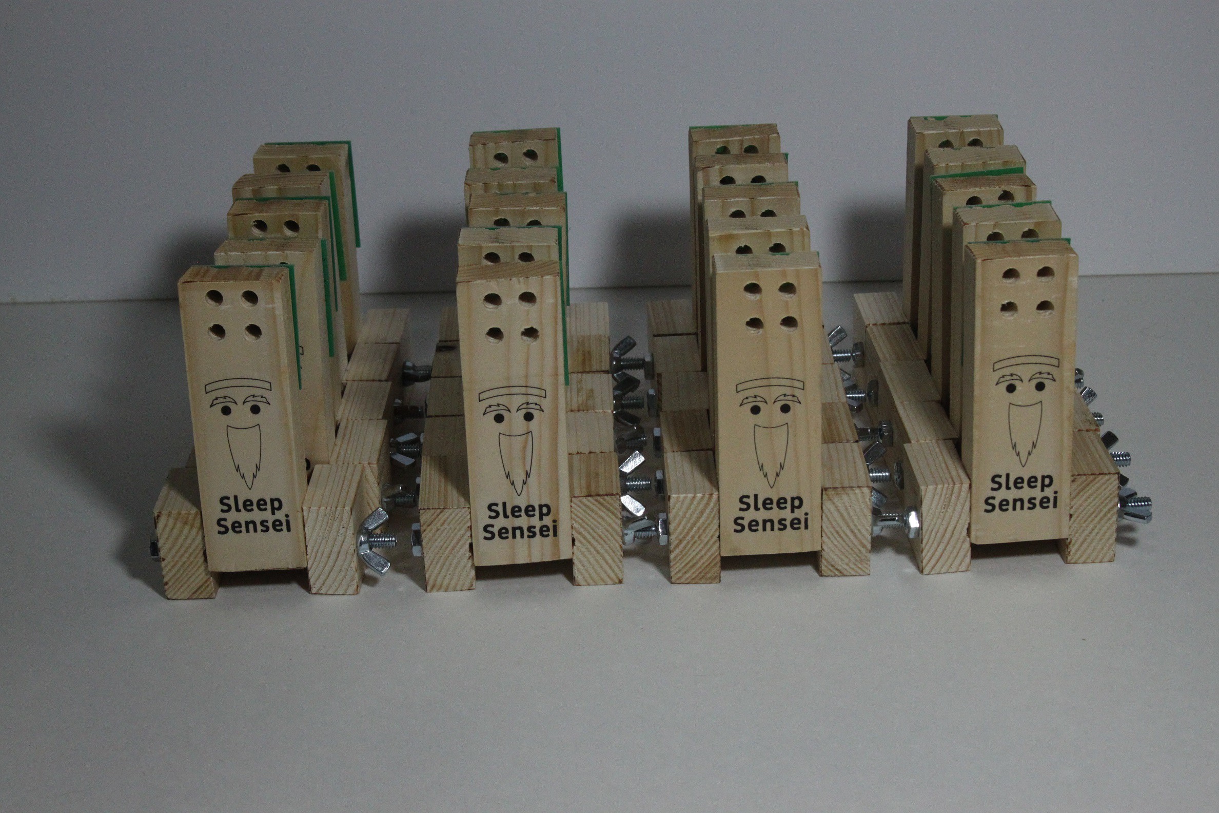
I wanted to test the product out in the wild and get feedback, so I came up with a (terrible) logo for the Sleep Sensei and made a small army of them!
The Sleep Sensei Study

At first, I gave my prototypes to a handful of friends for their feedback. They responded with things like “it seems to work” or “I think it might be helping.” Although it was great to get positive feedback, I wanted results that were a little more scientific. So I came up with a study of sorts.

Using this ad, I found several people on the reddit /r/insomnia community willing to try the device and provide me data on their sleep via a daily survey and seep tracking smartphone app. I had the users record data for 3 weeks without the Sleep Sensei, and I then sent the users the sleep coach device and had them record data for 3 weeks of sleep using the device.

I ended up sending out 20 Sleep Senseis, and I got decent data from 5 users. Here is a plot of the average time it took these users to fall asleep before and after using the Sleep Sensei:
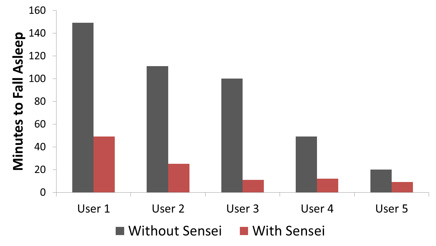
I have a detailed breakdown of each user’s data here.

Here is some of the feedback I got from the users:

“I think the quality of sleep has been improving, and I think that’s the Sleep Sensei. When I start having issues again I pull it out and it does help” – Alice S, TX

“I was really impressed with the [Sleep Sensei]- it cut the amount of time it took me to fall asleep by about half … I basically don’t have insomnia anymore and it feels that way” Marijke S, MA

“The [Sleep Sensei] allows me to fall asleep in at least under 30 minutes, sometimes even as few as 7 minutes, which is great for me! I would definitely recommend this device to anyone who is on the search for something new to help them fall asleep, someone who perhaps has tried every other sleep aid without finding anything that truly helps yet. The Sleep Sensei is awesome!” – Kate B, GA

“I’ve noticed a HUGE decrease in how long it takes me to fall asleep which has been wonderful! I really like the machine. It’s easy to use and works well.” – Kelly P, LA

Of course, this was not a clinical trial or very hard-sciency, but it gave me the confidence to try to make the Sleep Sensei into a real product by launching a Kickstarter!

The First Kickstarter

With a bit of confidence under my belt, I decided that I wanted to launch a kickstarter for the Sleep Sensei to get it into more hands.

I was tired of having to make my own wooden bases by hand, so I started working on a new design that could be fabricated by a vendor. I ended up trying out a bunch of concepts, such as:
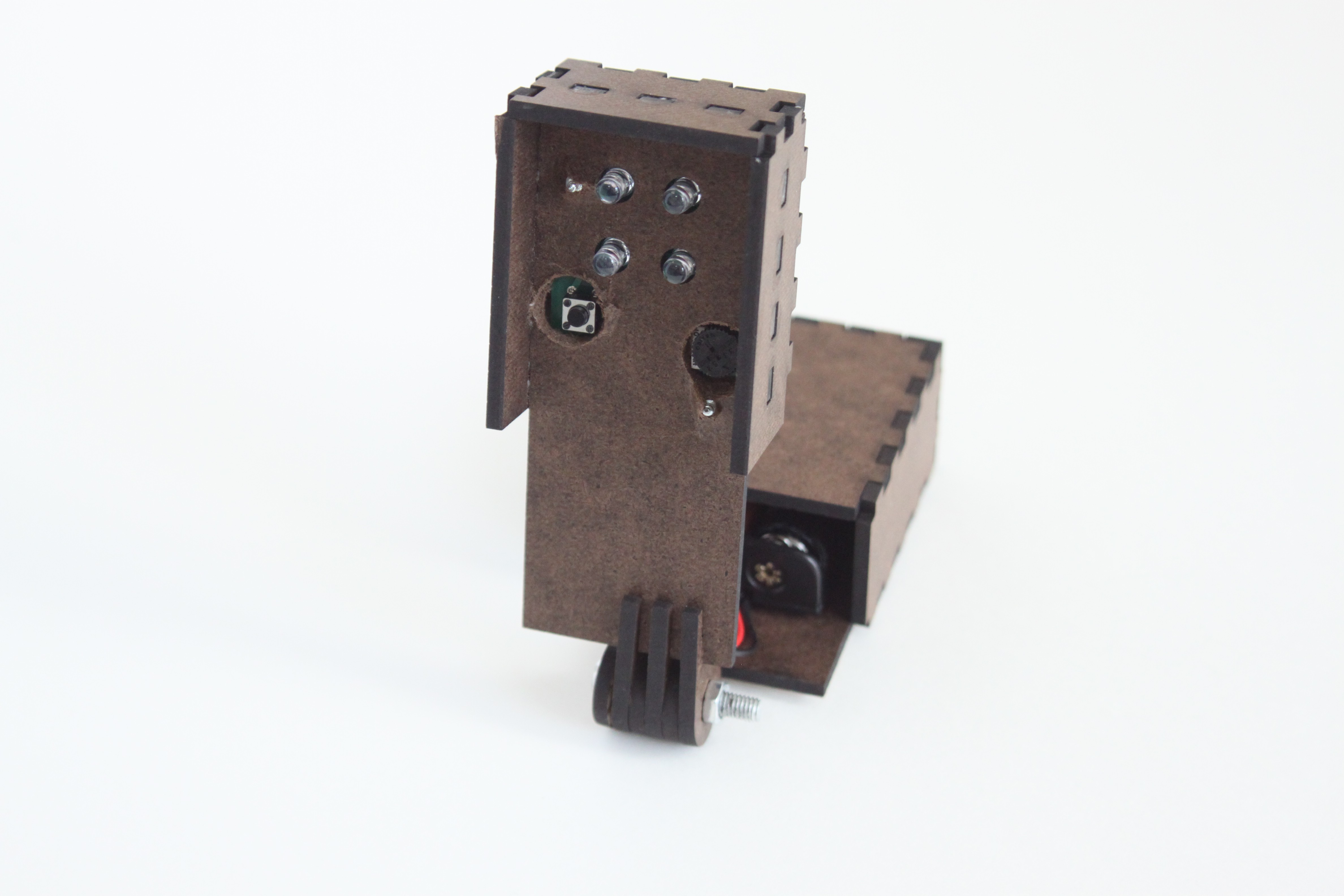
Split laser-cut design
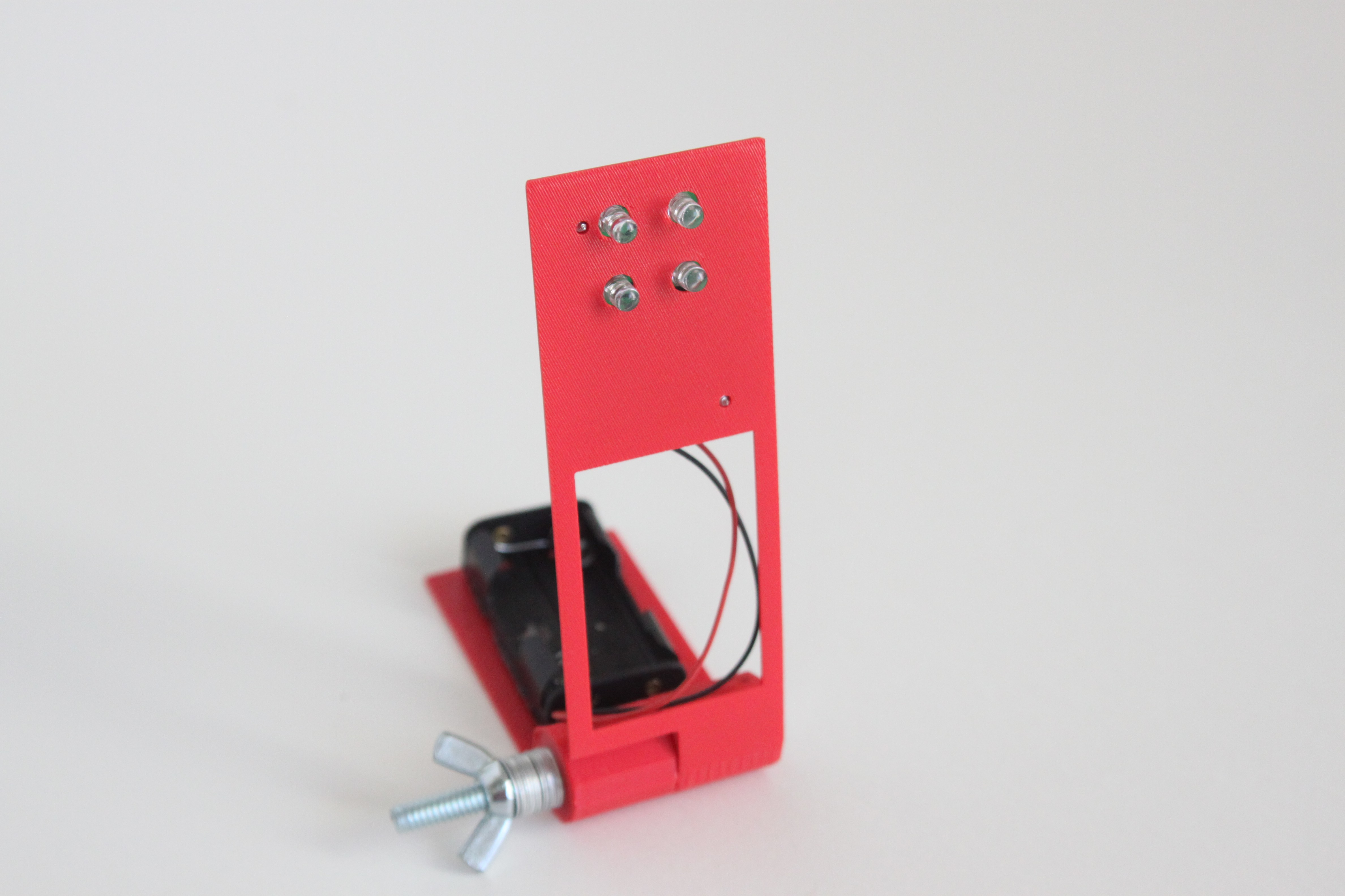
3D Printed minimalist
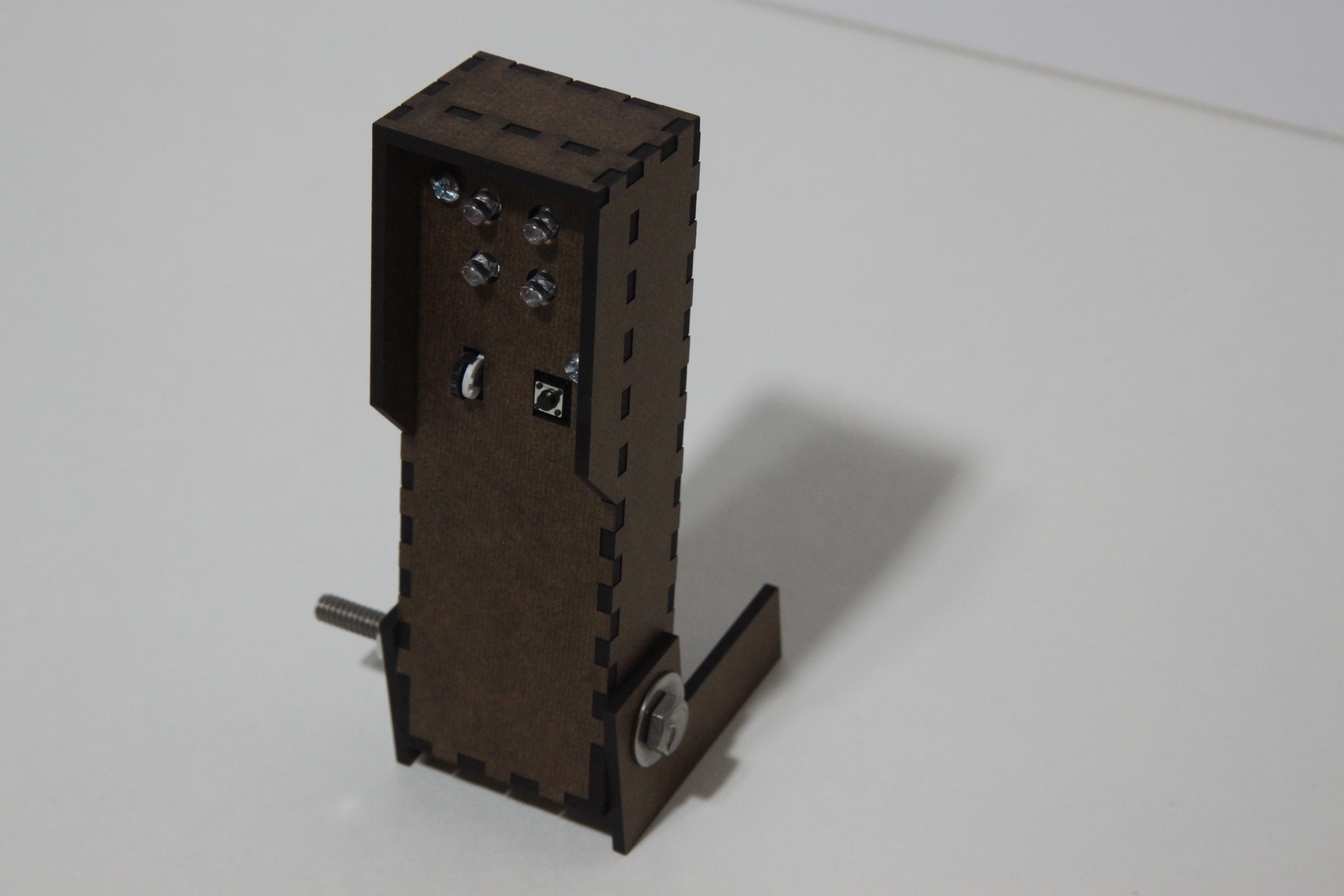
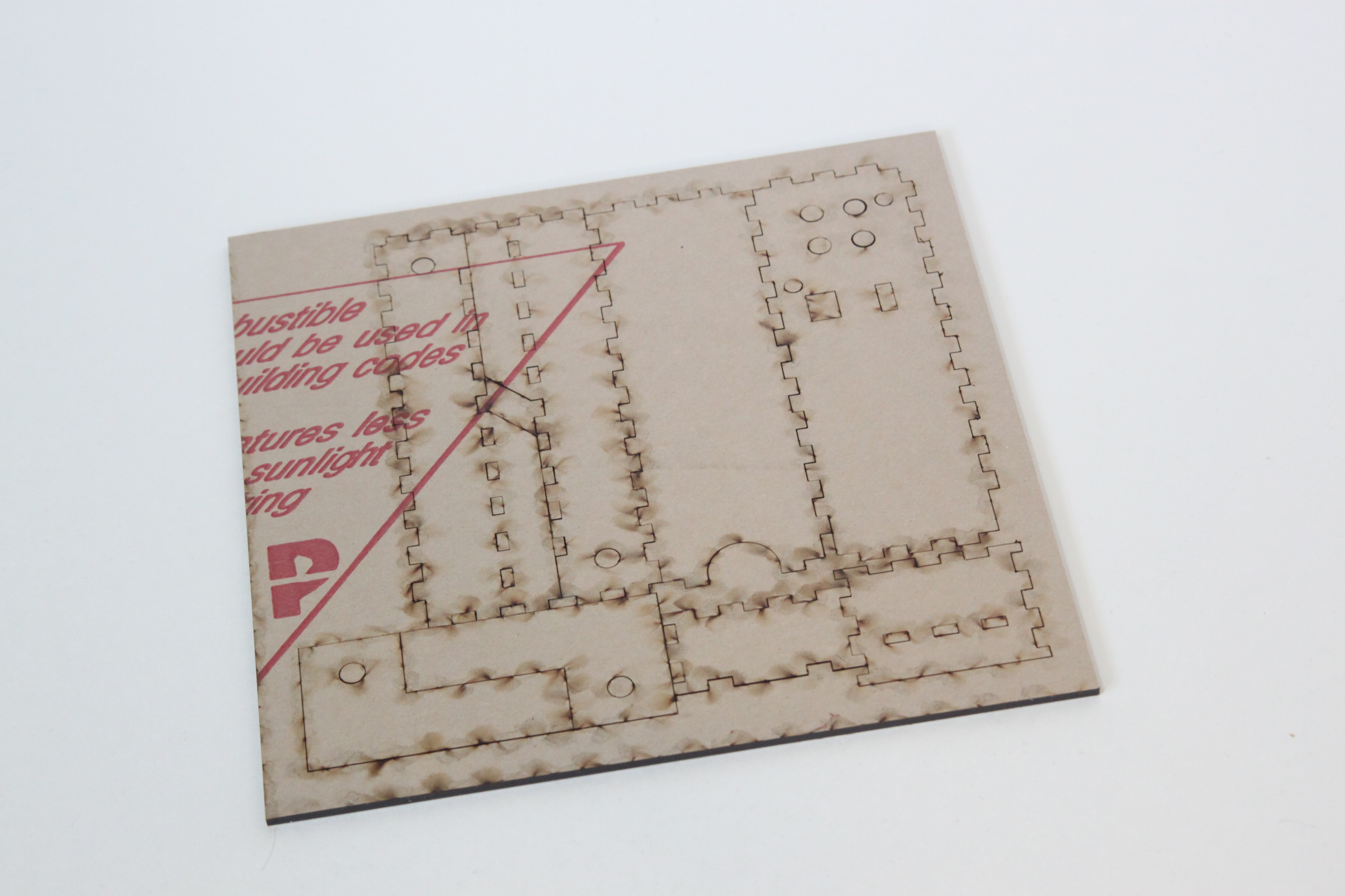
And what ended up being the winning concept, a laser-cut hinged design.

I decided to set my Kickstarter launch date as the same day as Houston Mini Maker Faire. This gave me a deadline, and I figured the Maker Faire would help me attract some backers.
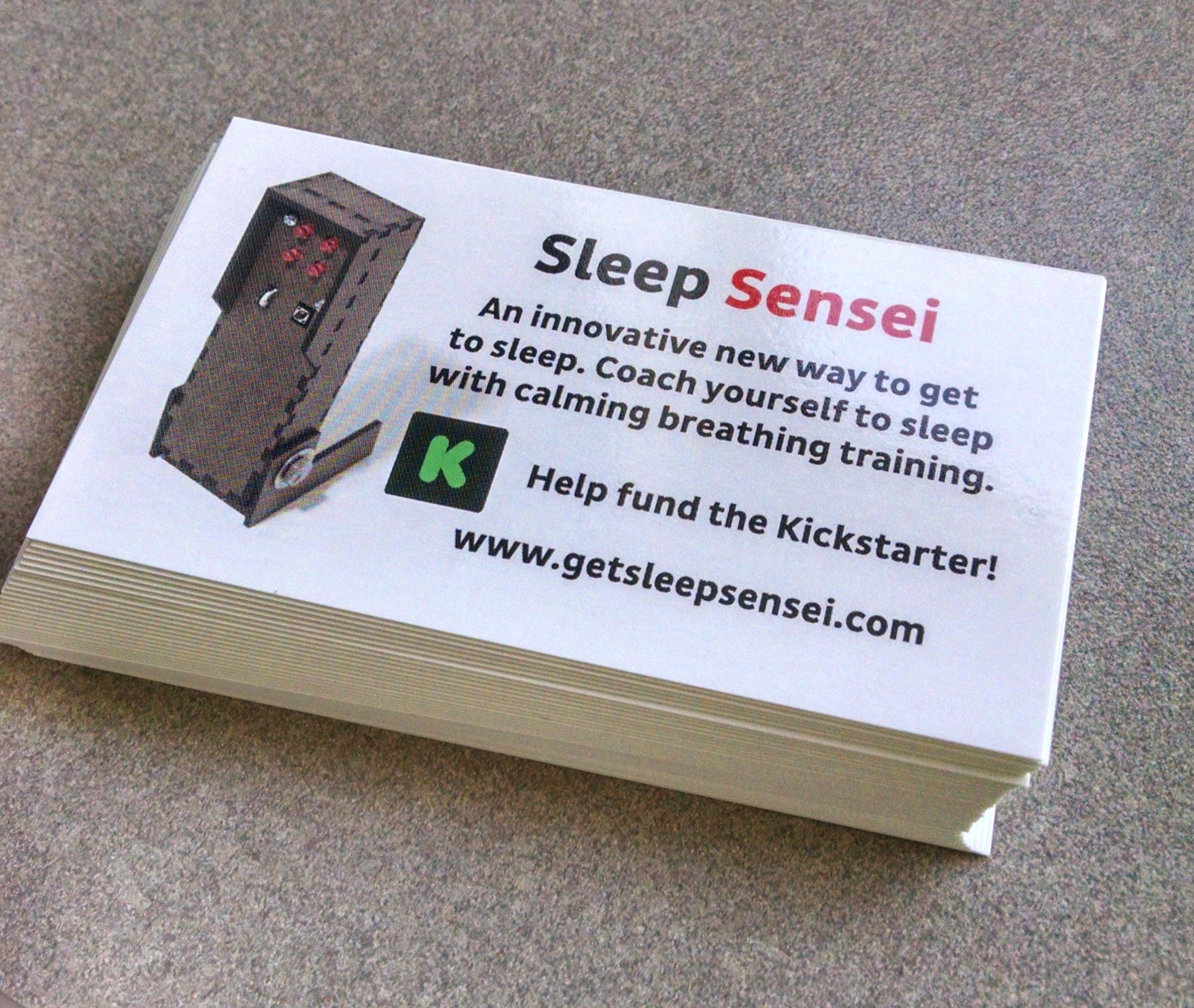
I made some business cards…
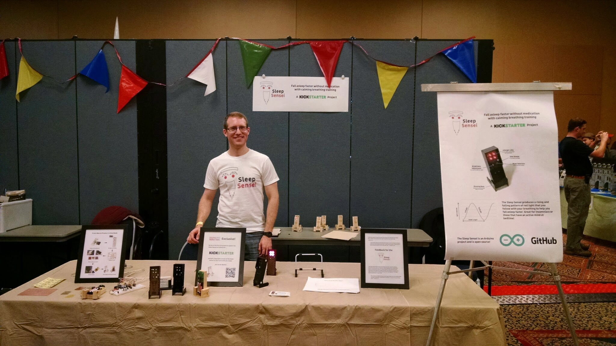
And set up a booth at the Maker Faire.

And I launched my Kickstarter page! However, it didn’t end up reaching the goal. I think several reasons factored in:

  • I made little effort outside of the Maker Faire to market the Sleep Sensei
  • I asked for way too much money. I had planned to have a vendor make and assemble all the PCBs, but this required a large volume of orders. I didn’t get anywhere close to what I needed.
  • The design was still rough around the edges

But, the failure of the first Kickstarter didn’t stop me, since Bay Area Maker Faire was just a few months away, and I had a couch to crash on in San Francisco. So I decided to improve the product and try again!

The Second Kickstarter

The New Strategy – Think Small

I figured that I still wouldn’t be able to get $25,000 for mass production, so I had to rethink how I would make the Sleep Sensei. I decided that if a reasonably small amount (less than 250) of Sleep Senseis were ordered, I would order the bare PCBs and solder the components myself. If quantities ordered exceeded these expectations, then the volume would be sufficient to put in a bulk order.

For example, I was quoted $8.27 per assembled PCB if only 100 were ordered, but the price went down to $3.57 each if I ordered 1000. The laser-cut bodies cost around $9 each shipped, and the mechanical components (knob, hinge) cost around $2. Adding in shipping, packaging, taxes, and Kickstarter fees, and the Sleep Sensei would sell at a loss at low quantities if I didn’t fabricate the boards myself!

The New Design

For the second Kickstarter, I wanted to have a finished improved design for the Sleep Sensei. One bit of feedback I heard from several people was that the default breathing pattern wasn’t right for them. Some complained the breathing rate was too slow, while others couldn’t keep up.

So, I wanted to allow the user to customize all aspects of the breathing pace: how long the breaths are at the start and end of the coaching session, and how long the session lasts. I had to rethink the design, since I wouldn’t be able to add all this functionality with just a button and a potentiometer. So, I switched up the design and opted for a rotary encoder with a built-in button.
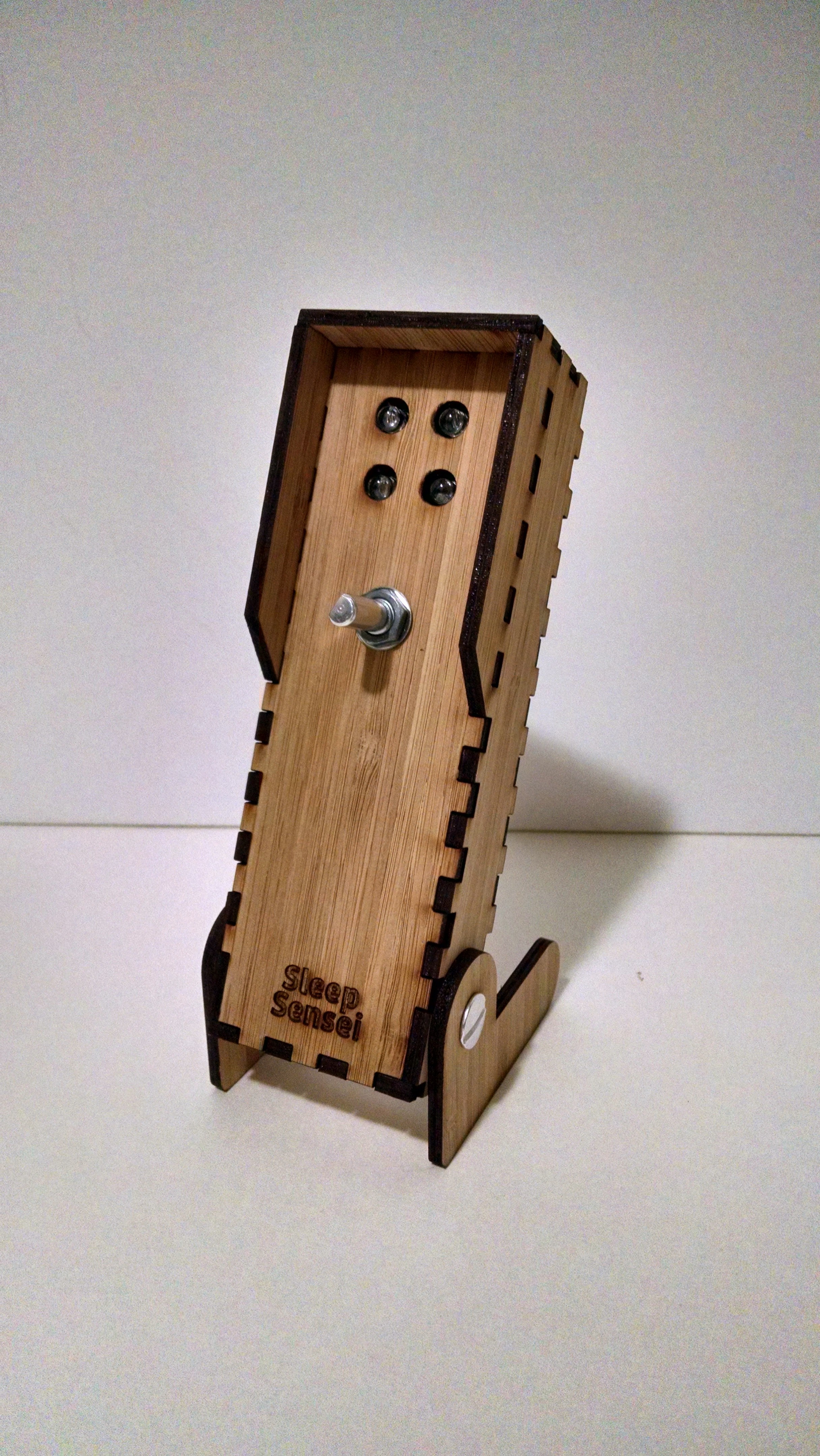
This gave me 3 forms of digital input: two directions of the knob and a button press. With this, I modified the code to include “menus” the user could activate in order to change the settings, and I made someinstructional videos to clarify how the process is done.

I also stared making the Sleep Sensei out of bamboo, since I liked the look and found the price to be comparable to using plastic.

Updating the Kickstarter

I also knew I needed a new logo and Kickstarter video. My girlfriend pitched in and came up with a sketch for a logo that I really liked:
I sent this over to a logo designer I found on Fiverr, and voila!

 

My girlfriend also helped me shoot the new video, with directing and writing help (and use of her Mac for some much-needed premium editing software).

I also found a reasonably priced professional product photographer on Fiverr, and had some nice shots of the Sleep Sensei taken.
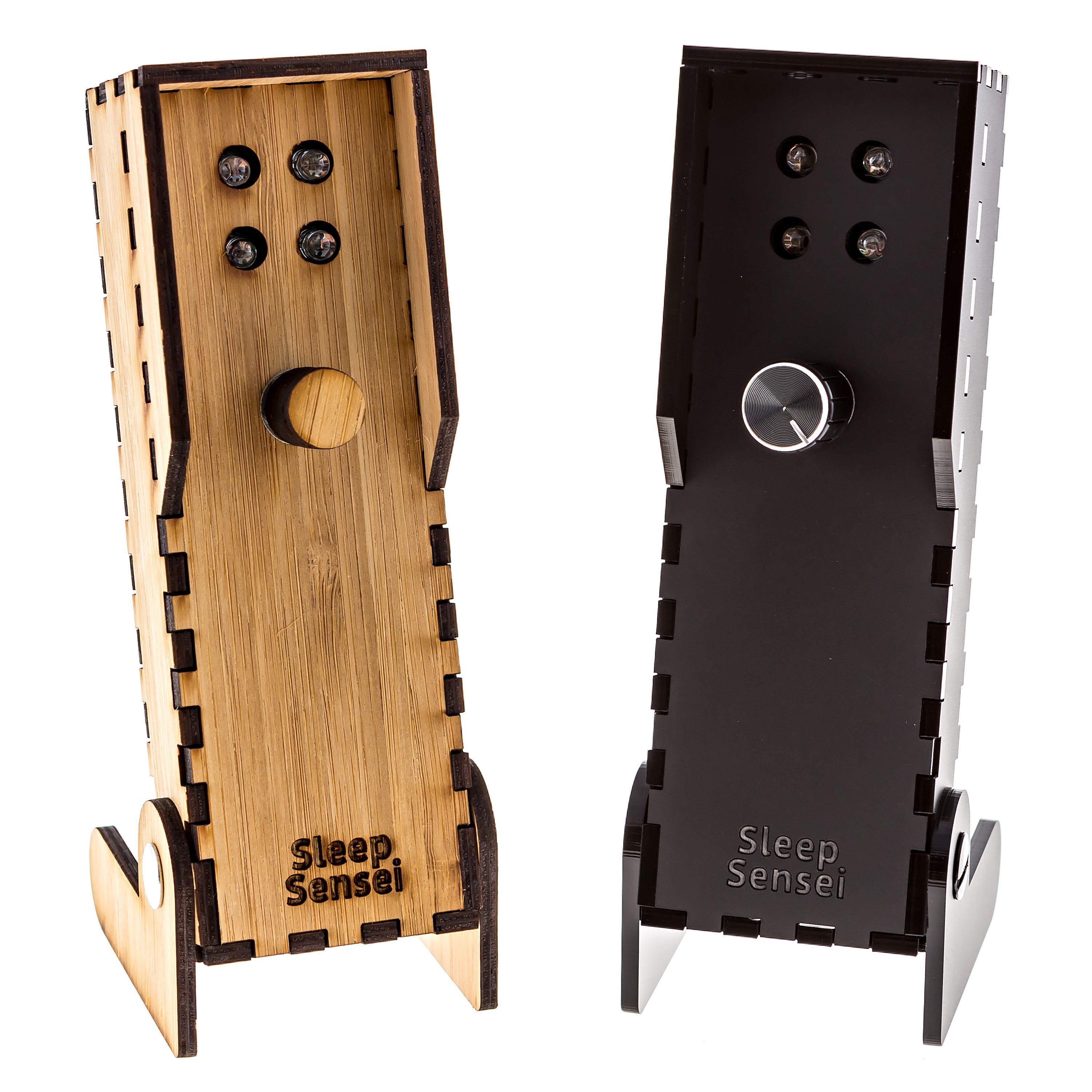
All in all, I wanted the new campaign to be more polished and professional, all while staying on a shoestring budget.

Marketing

This time, I wanted to be more proactive with the marketing of the Sleep Sensei, so I contacted Ponoko, the laser-cutting shop that produces the Sleep Sensei shell, and told them about the new Kickstarter. They were quite interested and ended up interviewing me and writing a post about it.

I also paid a couple of organizations that claim they will get you a bunch of backers through social media, but I did not get a single new backer as a result of their facebook posts and tweets. This seemed mainly because they sell the same service to hundreds of others, so your product is just one in a sea of many posts each day.
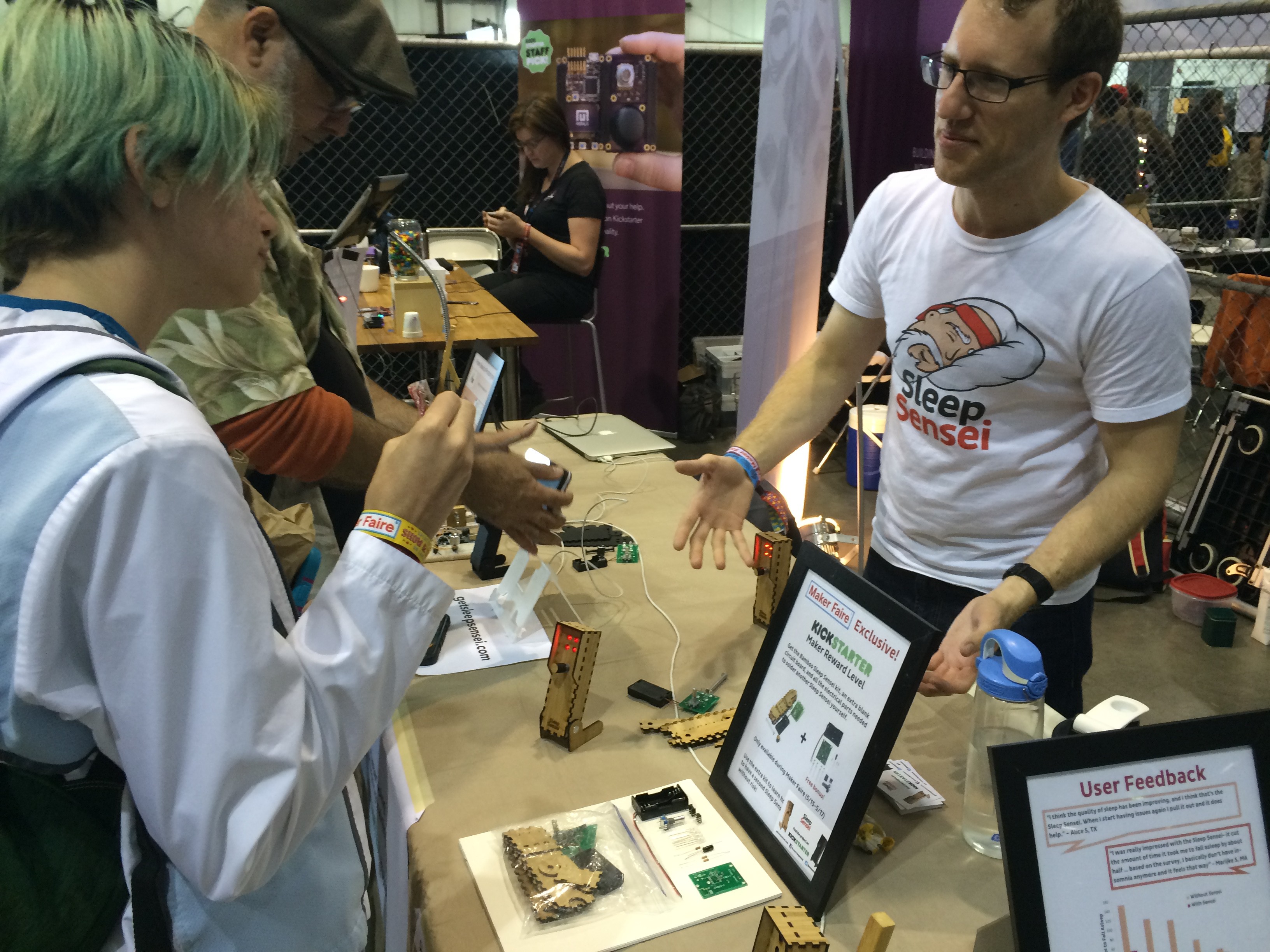
In the end, the Maker Faire ended up being the most valuable form of marketing, since I was able to show people the product and have them try it out in person. Most of my backers ended up coming out of the Bay Area, and I can assume that most of those backers were visitors to my Maker Faire booth.

After the Kickstarter

Once the Kickstarter was funded, I ordered all the things:
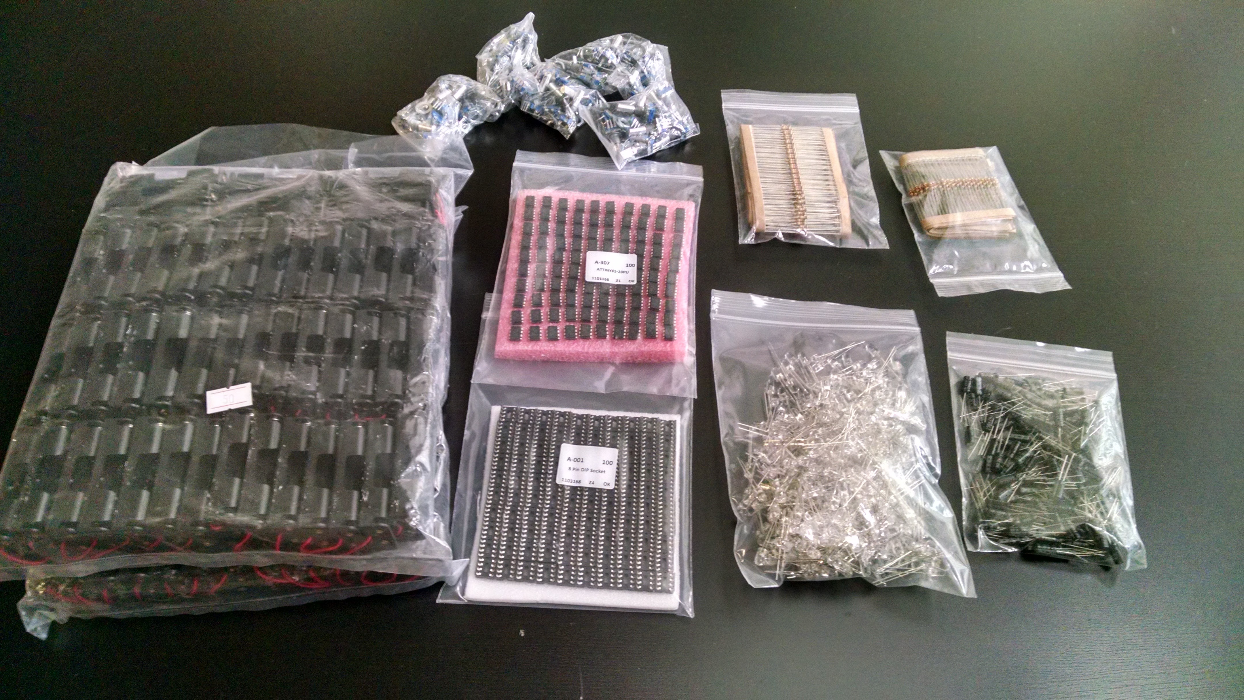
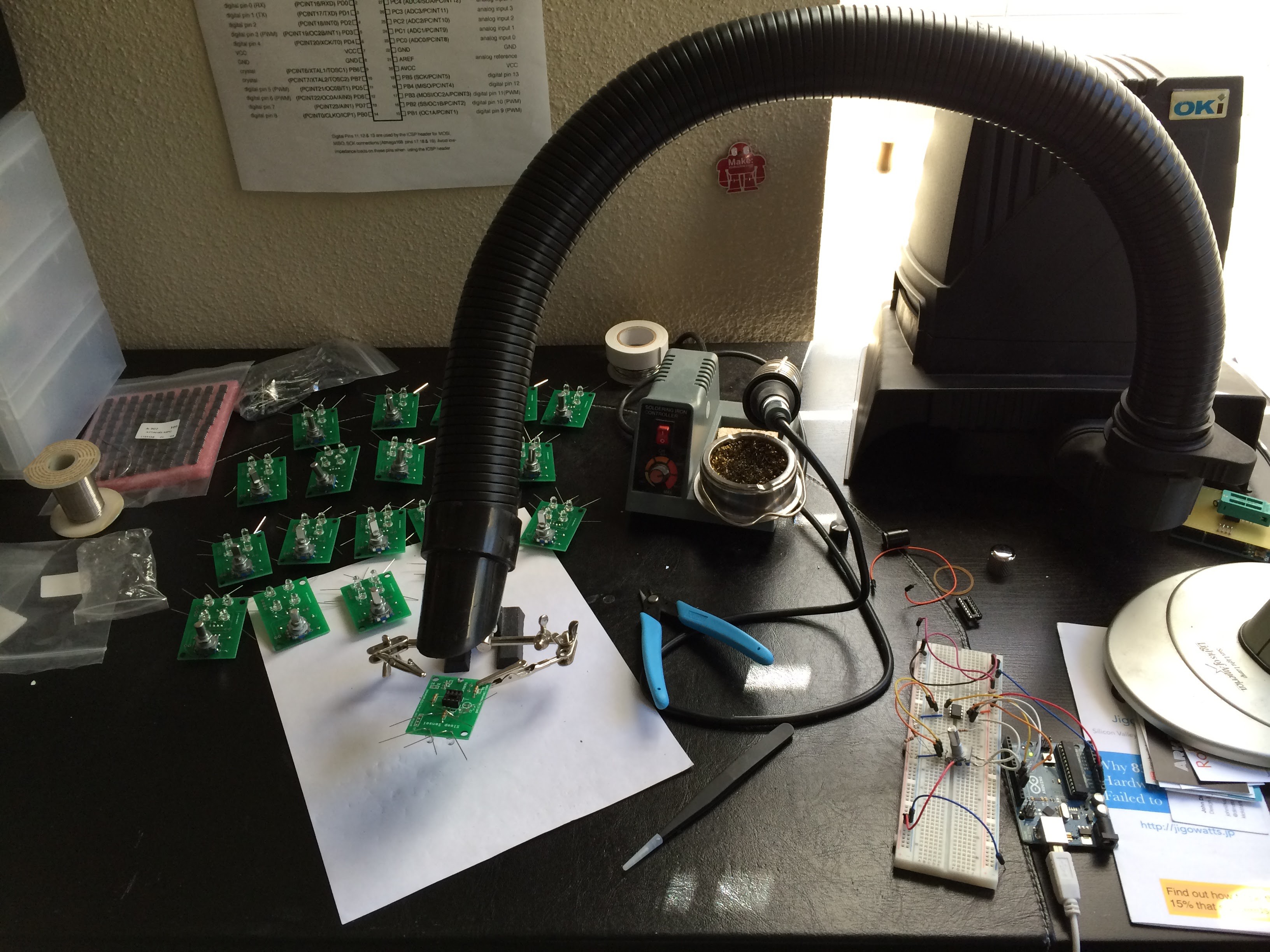
And got to work assembling the PCBs by hand:
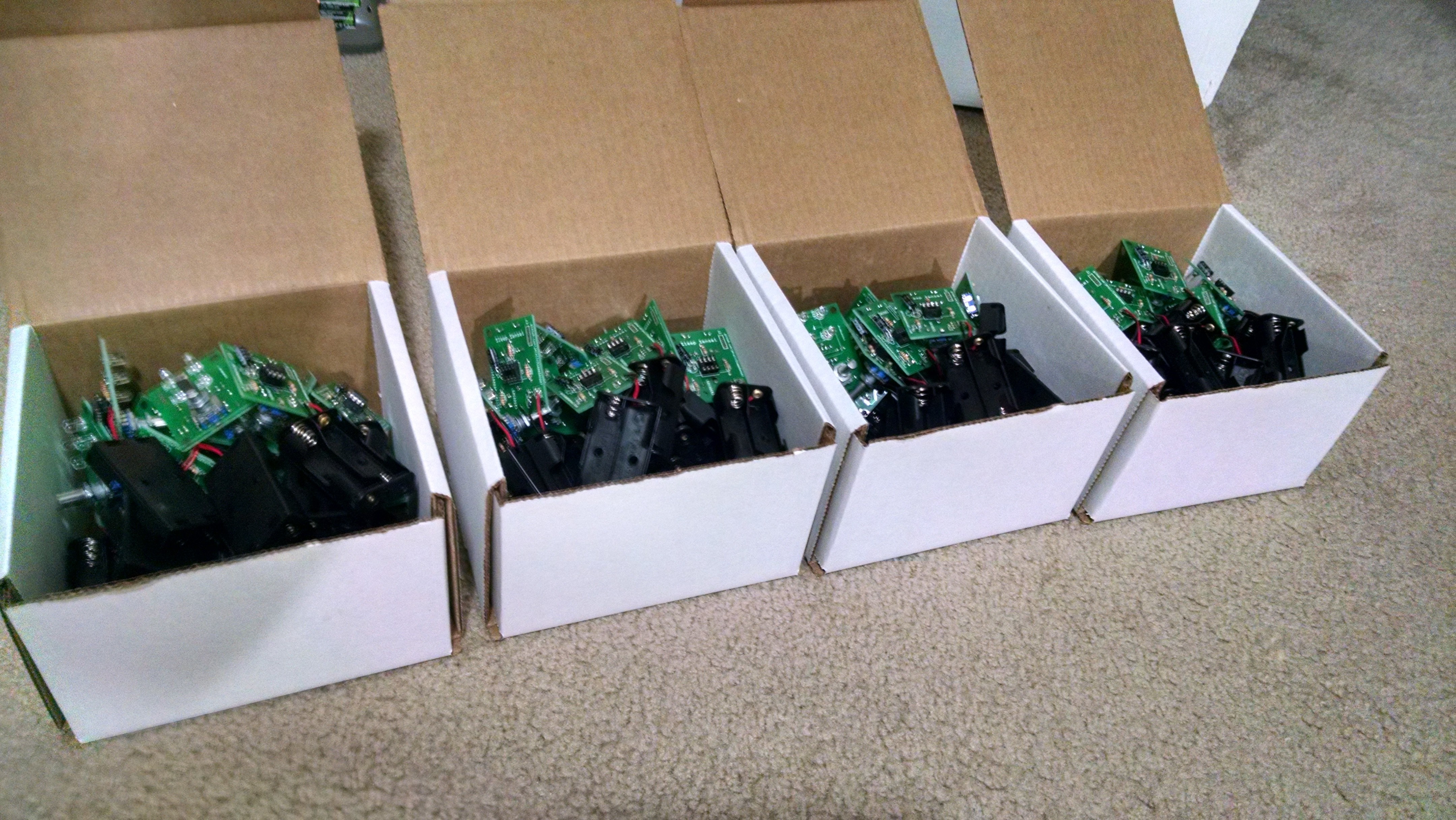
With my girlfriend’s help, we got all the lasercut components organized and ready to pack:
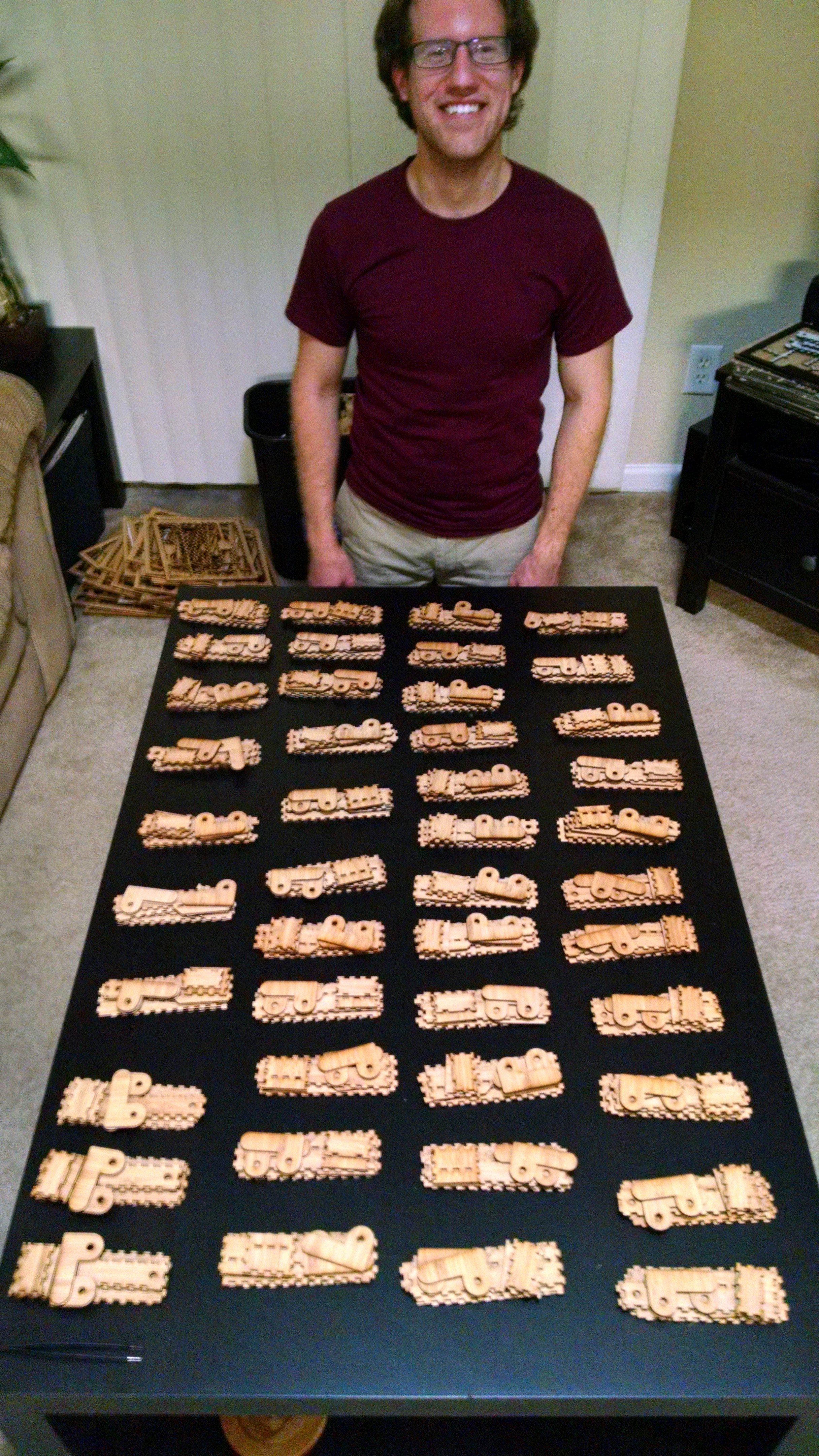
After a few weeks of assembling, packing, and shipping, all the Kickstarter rewards were out! I then did some research for a place to sell the Sleep Sensei going forward, and created a Tindie store.

Conclusion – You can’t do it alone

All in all, making the Sleep Sensei was a valuable experience. I got outside of my comfort zone to try to be a salesman, marketer, designer, video editor, photographer, web designer, electrical engineer, and mechanical designer. And I found that it was a lot of work!

I learned that if you want to be truly successful, you can’t do it all by yourself. For my first kickstarter, I tried to do it all on my own, and failed.

But the second time around, I had help from my girlfriend (logo designer, camerawoman, and great supporter), my brother Mark (editing of Kickstarter page, test subject, and Maker Faire booth hand), and paid help such as a professional photographer, a logo designer, and a music writer (for the video). I also was boosted by Ponoko’s newsletter piece about the new Kickstarter, and family and friends helped to share the Sleep Sensei on Facebook and Twitter. I even got some board design help from an electrical engineer friend at my workplace, and his feedback helped make the board smaller and more efficient.

I’m glad I was able to turn an idea of mine into an actual product, and I learned a lot along the way. Until the next great idea strikes, I’ll keep on tinkering!

Sonicare Head Holder

I am a big fan of the Sonicare toothbrush, but I’m not a fan of how large the heads are and how hard they are to store between uses. Since my girlfriend and I share a base, we always have a need to store the heads when we’re not brushing our teeth.

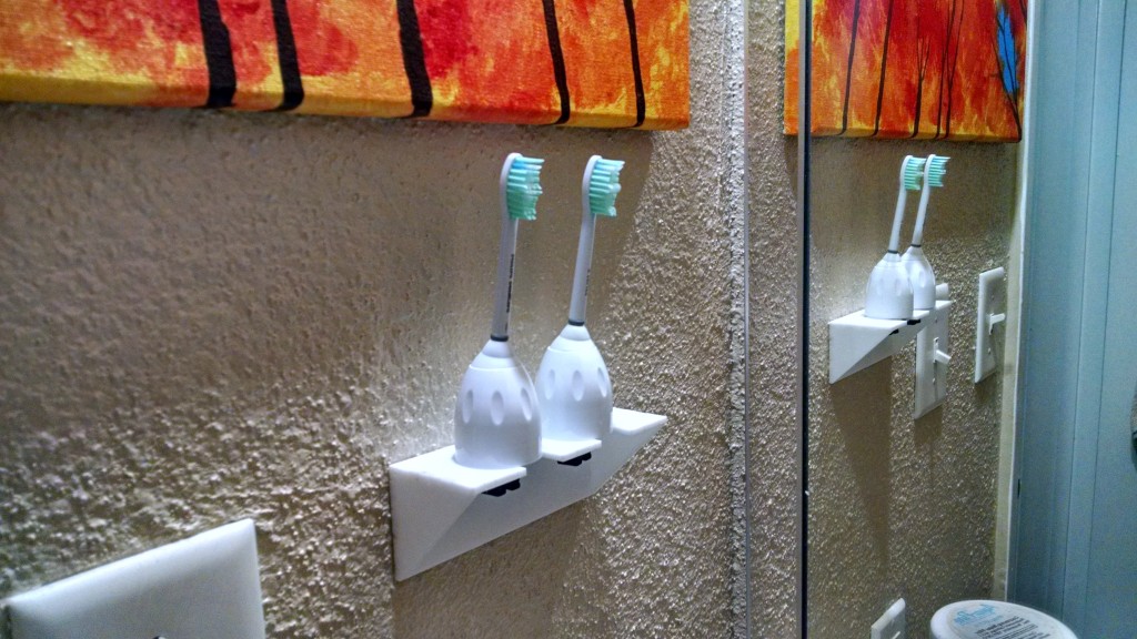
Since my bathroom is tiny, I wanted to be able to have something that would hang on the wall. I searched online, but I couldn’t find any existing products that would work. Thus, I decided to design my own hanging Sonicare head holder. This is what I came up with:

IMG_20150910_202701768_HDR

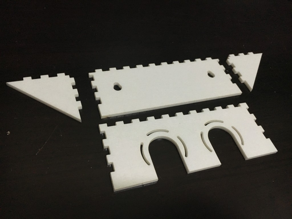
It is a laser-cut design made of white acrylic. The heads slide on, and the vents allow for any trapped moisture to escape. I used nodes on the interlocking portions to make the pieces better fit together.

IMG_2693

If you’d like to make this yourself, check out the design files on the GitHub page. You can also buy it ready-made it on my Ponoko page.

Arduino Pong

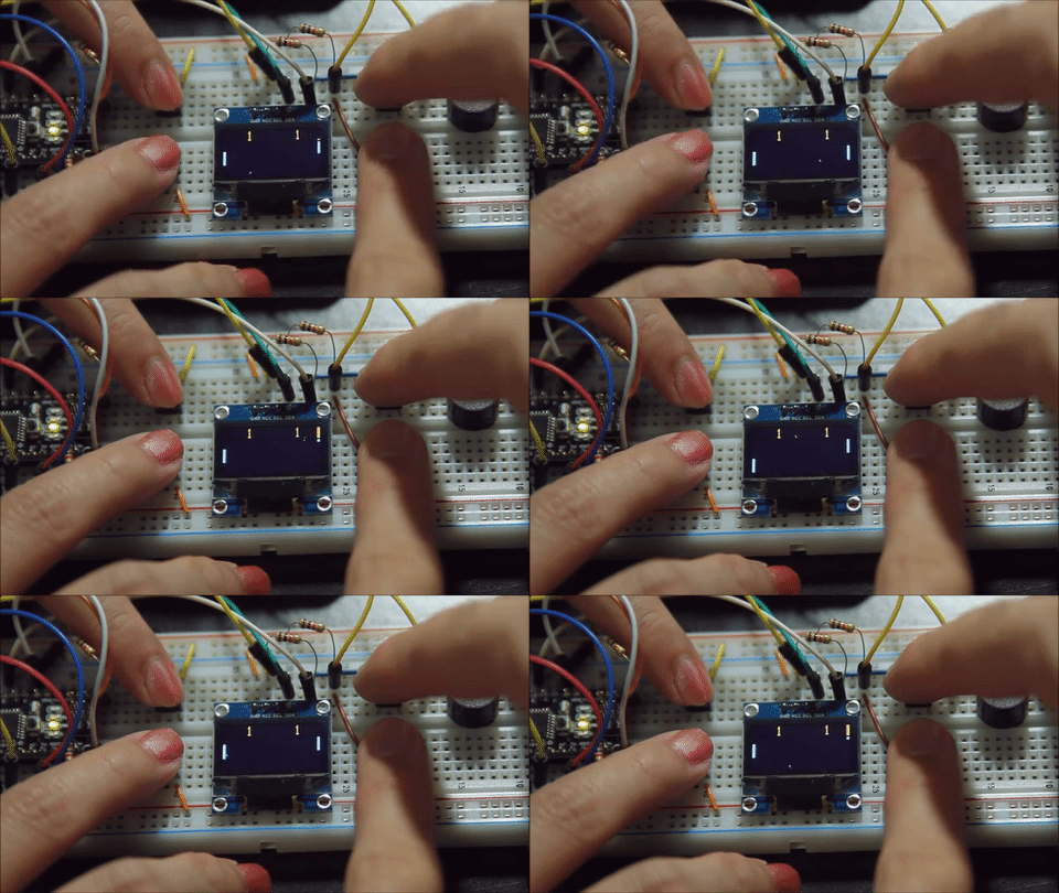
I recreated the classic game Pong with an Arduino.

Arduino_Pong_Gif

During my Arduino training sessions, I tasked my students to come up with a cool project using Arduino and various sensors and other electronics I had collected. This was my project entry.

Check out the video demo to hear the beeps!

Arduino_Pong_bb

This project takes advantage of Adafruit’s SSD1306 OLED driver library and GFX Library.

For all the technical details, code, and schematic, check out the GitHub page.

Valve Pressure Cycling System

The Task & Background

One of my goals in the ATO Lab was to help other GE Oil & Gas labs automate testing and acquire data using LabVIEW-based designs. One of our sister labs is in Aberdeen, Scotland, and they do similar tests to those done in Houston. One of their electrical technicians wanted to learn LabVIEW, so I was sent out there for some hands-on learning.

I like teaching and tutoring, and I have found that one of the best ways to learn how to do something is to find a project that requires the target subject and work through it. So we brainstormed some ideas for automated systems that would benefit the lab, and we decided to make a system that would automatically perform pressure cycles on a valve.

Each valve that is tested in the lab must undergo a certain number of body pressure cycles. These cycles involve pressurizing the bore of the valve with nitrogen gas, holding pressure, checking for pressure drop, and releasing pressure. Most valves undergo 50 or more of these cycles, so it is very beneficial to automate this tedious process.

The Process

This project was primarily a learning exercise, so I sat down with the technician and helped him set up a cRIO and get some basic I/O working with a relay module and an LVDT position sensor. I then helped him install our preferred revision control system software (TortoiseSVN) and we did a checkout and a commit. From there, with the technician at the keyboard, we created the valve cycling system LabVIEW software from scratch using a simple state machine architecture.

The Hardware

IMG_0661

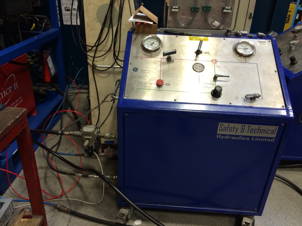
We modified an existing pump system and added high pressure air-actuated valves for pump control, pressure supply, and bleed. We also added a pressure transducer to read the pressure inside the valve, which is crucial for automated control.

For the electrical controls, we used a cRIO with an analog input module, a relay module, and a digital input module. The relay module allowed for the control of solenoid valves which would supply air to the air-actuated valves.

These normally-closed solenoid valves obtained their power through a circuit that passed through an E-stop button. If this button is pressed, all the solenoid valves relieve pressure, causing their corresponding air-actuated valves to close and for the pump to stop. A digital input line from the E-stop informed the software if the E-stop had been pressed.

The Software

Over a two week period, we created a state machine in LabVIEW that would perform the various steps in the cycle and check for pressure drop, timeout, and a variety of other errors. After showing the technician the basic architecture, I had him figure out the various state transitions and error checks needed to make the system work.

Testing

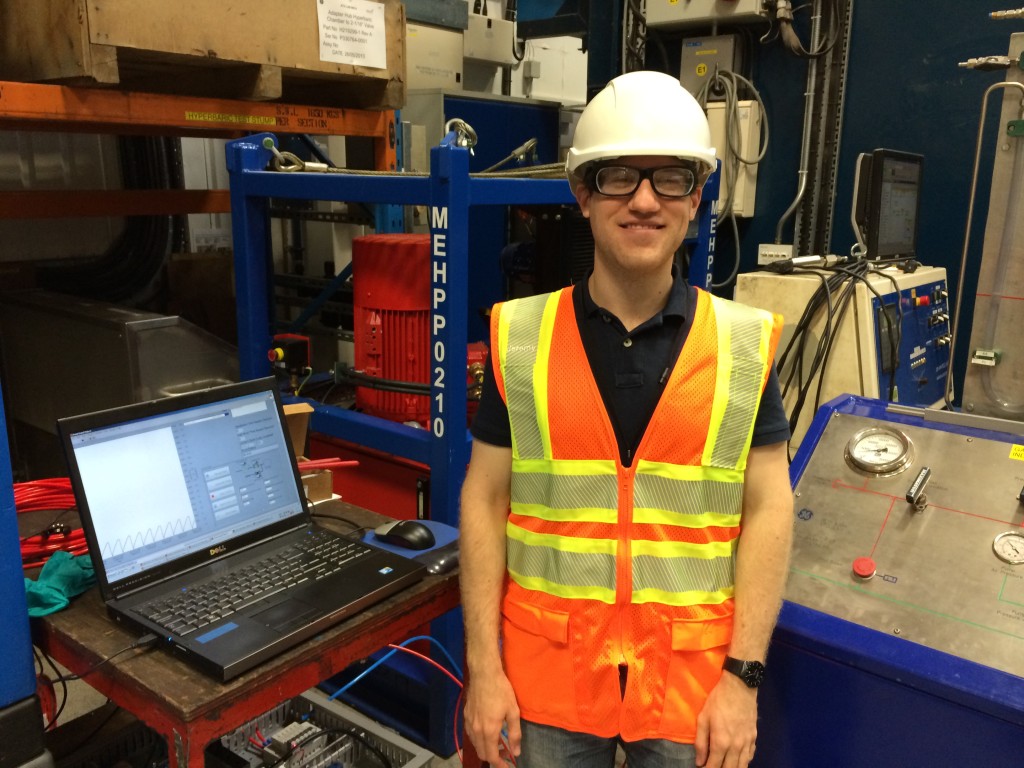
We got the system up and running and tested it on one of the valves on the shop floor. You can see me next to the interface in the photo below. The screen shows a strip chart of the valve pressure as well as the valve cycling controls.

IMG_0658

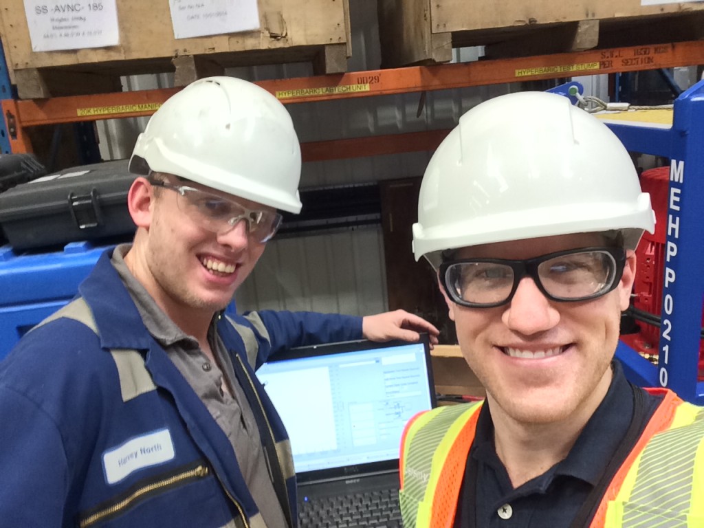
Overall the project was a success! The system ran well, and the technician learned some LabVIEW and how to set up and troubleshoot a cRIO Real Time system. Below is a photo of a proud technician and his creation:

IMG_0660

Work Training

 Arduino Training Sessions

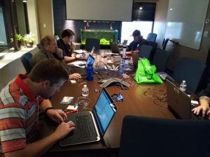
While at the ATO lab, I wanted to share some of the knowledge I had acquired through my hobby projects. Many coworkers were interested in some of the projects I had been working on at home, and they wanted to know how they could do something similar. So I decided (with permission) to take a couple hours out of the week for hands-on Arduino training sessions.

IMG_20160412_161754

Starting at the most basic level of installing the software and running the blink sketch, I walked the class through topics such as:

  • Digital inputs and outputs
  • Reading from analog sensors
  • Scaling analog readings
  • Serial communication
  • Using PWM to control LED brightness
  • Installing external libraries
  • Reading from digital sensors
  • Outputting to a screen using the I2C protocol
  • If statements, for loops, while loops, functions

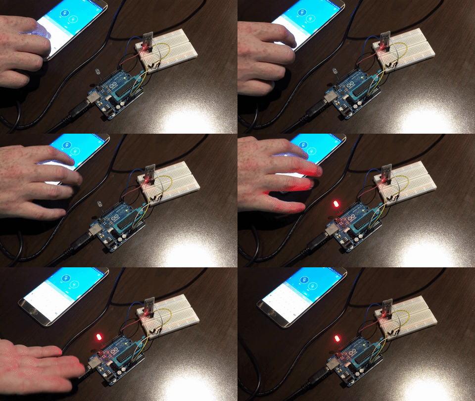
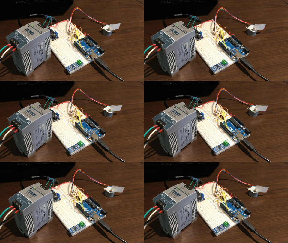
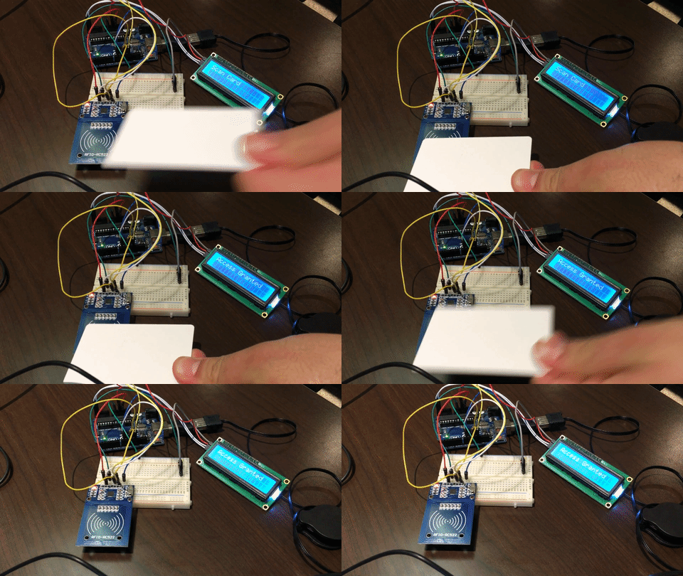
After two weeks of training, I had my students come up with a project using some of the parts I had. Here is what they came up with :

A bluetooth-controlled light

A bluetooth-controlled light

A stepper motor clock

A stepper motor clock

A badge access system

A badge access system

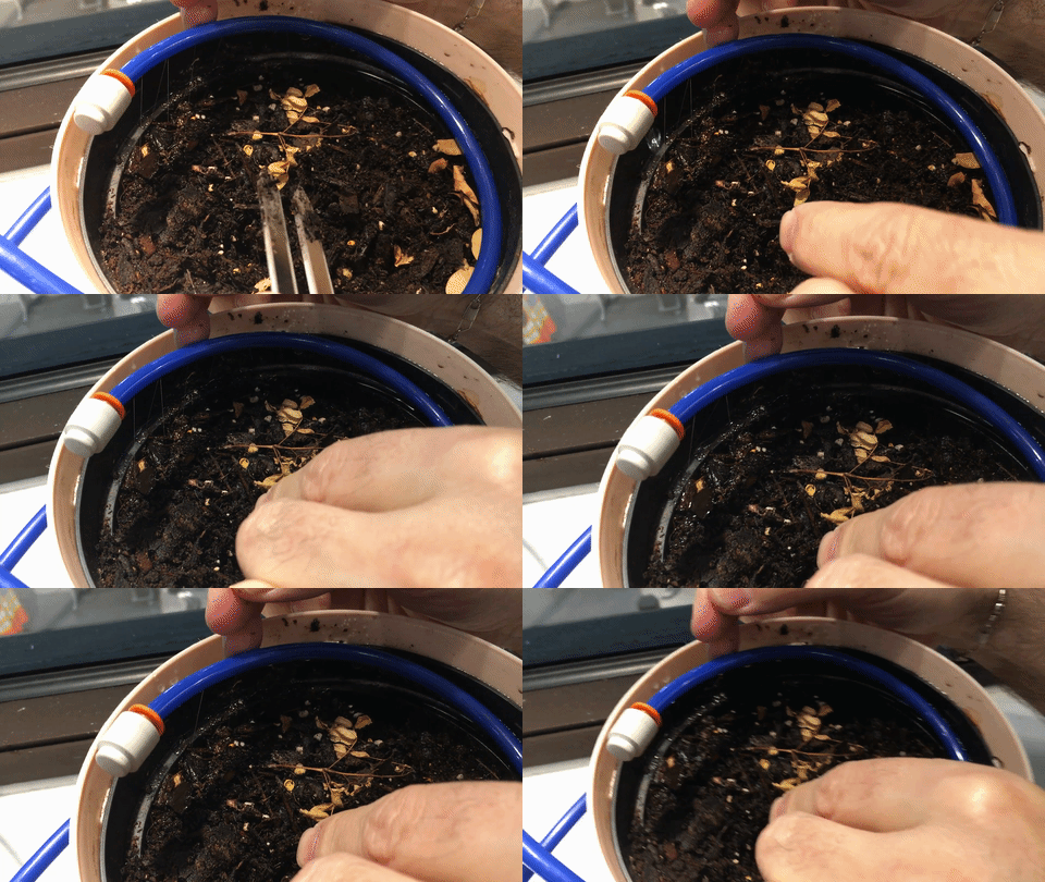
Automated plant watering

Automated plant watering

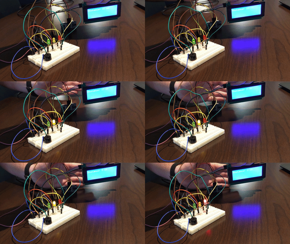
A parking sensor for the garage

A garage parking sensor


LabVIEW Real Time Training Rig

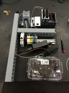
When you purchase a full license of the LabVIEW development system, you get access to self-paced online training. This is pretty great and allows for some good hands-on learning through coding exercises… that is until you reach the Real Time section which requires a specific set of hardware to actually perform the tasks.

IMG_0109

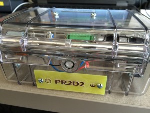
Thus, I made PR2D2, named after a standard temperature/pressure test we do in the lab (PR2) and everyone’s favorite droid. This board contains all the hardware needed to complete LabVIEW Real Time 1 and 2, enabling several developers in the lab to learn hands-on on their own schedule without the need to travel to a training center.

IMG_0006

I also made a label for it using our circuit board mill, with a Star Wars font and rebel alliance symbol for good measure.

Formal Training and Certifications

I have a LabVIEW Certified Developer status and have completed the following LabVIEW training modules:

  • LabVIEW Core 1
  • LabVIEW Core 2
  • LabVIEW Core 3
  • LabVIEW Real Time 1
  • LabVIEW Real Time 2

I am trained and certified to operate jib and gantry cranes up to 50 ton.

I have been trained and certified in Swagelok fittings and tube bending.

I have the radiation training certification necessary to operate an XRF tool.

I have had formal training and practice in GD&T.